background image

– 5 –

3-2. Connecting the Cable to the Printer

Note that the interface cable is not provided. Please use a cable that meets specifications.

3-2-1. USB Interface Cable

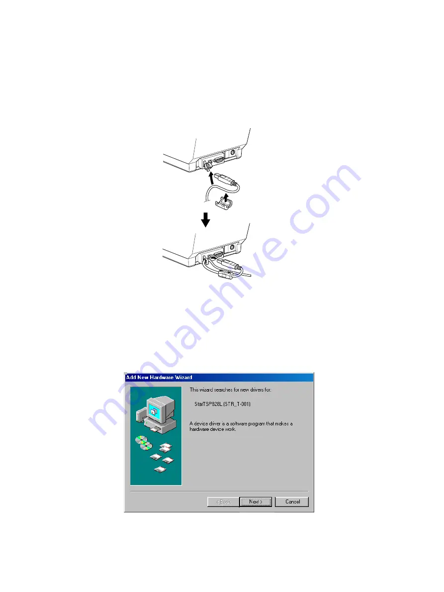
Affix the ferrite core onto the USB cable as shown in the illustration below and make sure to pass
the cable through the cable support as shown in the illustration.

Note:

The dialog shown below may appear on your PC screen if your PC is running
Windows 98 or Me, and if you turn ON the power of the printer for the first time
while the PC and the printer are connected with the USB cable. In this case, refer
to the software manual on the CD-ROM, in the following directory: Documents
folder.

Summary of Contents for TSP828L Series

Page 1: ...Label PRINTER TSP828L SERIES Hardware Manual ...

Page 2: ...pplicables aux appareils numériques de la classe A prescrites dans le Règlement sur le brouillage radioélectrique édicté par le ministère des Communications du Canada The above statement applies only to printers marketed in Canada CE Manufacturer s Declaration of Conformity EC Council Directive 89 336 EEC of 3 May 1989 This product has been designed and manufactured in accordance with the Internat...

Page 3: ...usting the Sensors 27 6 Preventing and Clearing Paper Jams 31 6 1 Preventing Paper Jams 31 6 2 Removing Paper Jam 31 7 Periodic Cleaning 32 7 1 Cleaning the Thermal Head and Ground Hardware 32 7 2 Cleaning the Printer Cover Paper Guide and Peeler Sensor 32 8 Specifications 33 8 1 General Specifications 33 8 2 Interface 34 8 3 Electrical Characteristics 34 8 4 Environmental Requirements 35 8 5 Reli...

Page 4: ...original box and all the packing materials just in case you need to pack the printer up again and send it somewhere at a later date Printer Springs Tension shaft Ferrite core for dual interface model Power cable AC Adapter CD ROM Setup sheets Thermal label roll paper Ferrite core for parallel interface model Fastener for parallel interface model Tension shaft holders Note When using a thermal labe...

Page 5: ...ter of the front cover to open the printer cover Power connector For connection of the AC adapter Never unplug the AC adapter while the printer is on RS 232 interface For connection to a host computer However it cannot be connected concurrently with USB USB interface For connection to a host computer However it cannot be connected concurrently with RS 232 Parallel Interface Model Power connector F...

Page 6: ...t the surrounding area is clean dry and free of dust Make sure that the printer is connected to a reliable power outlet It should not be on the same electric circuit as copiers refrigerators or other appliances that cause power spikes Make sure that the room where you are using the printer is not too humid WARNING Shutdownyourequipmentimmediatelyifitproducessmoke astrangeodor orunusual noise Immed...

Page 7: ... Me and if you turn ON the power of the printer for the first time while the PC and the printer are connected with the USB cable In this case refer to the software manual on the CD ROM in the following directory Documents folder 3 1 2 RC 232 Interface Cable ConnecttheRC 232interfacecabletoaRS 232portofyour PC 3 1 3 Parallel Interface Cable Connect the parallel interface cable to a parallel port of...

Page 8: ...ustration below and make sure to pass the cable through the cable support as shown in the illustration Note The dialog shown below may appear on your PC screen if your PC is running Windows 98 or Me and if you turn ON the power of the printer for the first time while the PC and the printer are connected with the USB cable In this case refer to the software manual on the CD ROM in the following dir...

Page 9: ...utlet 2 Connect the interface cable to the connec tor on the rear panel of the printer 3 Tighten the connector screws 3 2 3 Parallel Interface Cable 1 Make sure the printer is turn off 2 For only the parallel interface model affix the ferrite core onto the cable as shown in the illustration below 3 Pass the fastener through the ferrite core 4 Loop the fastener around the cable and lock it Use scis...

Page 10: ... start Windows 2 Insert the supplied CD ROM Drivers and Utilities into the CD ROM drive 3 Follow the instructions that appear on the screen 4 The dialog shown in the illustration indicates that the procedure has been completed Click OK The dialog that appears on the screen varies with your system This completes the installation of the printer software A message will appear prompting you to restart...

Page 11: ... from the AC outlet 1 Connect the AC adapter to the power cable Note Use only the standard AC adapter and power cable 2 Connect AC adapter to the connector on the printer 3 Insert the power cable plug into an AC outlet CAUTION When disconnecting the cable take hold of the cable connector to pull it out Releasing the lock makes it easy to disconnect the connector Pulling the cable excessively could...

Page 12: ...inter so that the power outlet it is plugged into is nearby and easy to access When an Switch blind is affixed to the printer above the power switch the ON OFF marks of the power switch may be hidden If this occurs remove the power cord from the outlet to turn the printer OFF Note ThedialogshownbelowmayappearonyourPCscreenifyourPCisrunningWindows 98 or Me and if you turn ON the power of the printe...

Page 13: ...ension folders and two springs otherwise a paper jam could result 1 Check that dip switch 1 8 is ON default thermallabelrollpaper SeeChapter9for instructionsonhowtosetthedipswitches 2 Turn ON the power switch of the printer 3 Push the front cover downward 4 Openboththeouterandinnerprintercovers 5 Adjust the roll paper guide to the width of the roll paper ...

Page 14: ...a label that is within 150 mm from the end of the roll paper and place the roll paper in the direction shown 7 Pull out the end of the backing paper to wards you 8 Close the inner cover and firmly press both its ends ...

Page 15: ...per 12 Press the FEED button to bring up the leading edge of the roll paper Note If the leading edge of a label is not detectedafter300mmormoreofthe roll is fed the printer will determine that it is out of paper and will stop Redo the loading of the roll paper from the beginning 13 After printing the printer will eject a label as shown and flash the red ERROR lamp 14 Remove the label The ERROR lam...

Page 16: ...nd two springs otherwise a paper jam could result 1 Check that dip switch 1 8 is ON default thermallabelrollpaper SeeChapter9for instructionsonhowtosetthedipswitches 2 Turn ON the power switch of the printer 3 Push the front cover downward 4 Open both the outer and inner printer cov ers 5 Adjust the roll paper guide to the width of the roll paper ...

Page 17: ...ut the end of the backing paper to wards you 8 Check that the power switch is ON 9 Leavingthebackingpaperasis closeboth the outer and inner covers Push both sides of the printer cover with your hands as shown until the printer cover is securely closed 10 Cuttheportionofthebackingpaper which extendsfromthefrontcover alongthetear bar ...

Page 18: ...t it is out of paper and will stop Redo the loading of the roll paper from the beginning 12 The printer will eject a label as shown 3 6 3 Thermal Roll Paper 1 Check that dip switch 1 8 is OFF thermal roll paper 2 Turn ON the power switch of the printer 3 Push the front cover downward 4 Open both the outer and inner printer cov ers 5 Adjust the roll paper guide to the width of the roll paper ...

Page 19: ... paper is 100 to 150 µm it is not necessary to install the tension bar Note Firmly press the tension bar until it clicks into place Note To remove the tension bar use a slot screwdriver to undo the clips at each end of the tension bar as shown Then remove the tension bar 7 Place the roll paper in the direction shown Click ...

Page 20: ...ectedafter300mmormoreofthe roll is fed the printer will determine that it is out of paper and will stop Redo the loading of the roll paper from the beginning 12 The printer will eject a label as shown Caution Symbol This symbol is placed near the thermal print head to indicate that it may be hot Never touch the thermal print head immediately after the printer has been used Let the thermal print he...

Page 21: ...e thermal head from static electricity Never directly touch the IC The printing quality and working life of the thermal head cannot be guaranteed if any paper other than that recommended is used In particular paper containing Sodium Potassium Chlorine may drastically reduce the working life of the thermal head Please exercise caution Do not operate the printer if there is moisture on the front sur...

Page 22: ... 5 mm to 112 0 5 mm Core inner outer diameters coreinnerdiameter ø25 4 1mm coreouterdiameterø32 1mm Finished state of label roll paper Make sure the finished state of the label roll paper meets the following conditions 1 Face the label surface of the thermal label paper outward of the roll 2 Do not allow the core to protrude from the ends of the label roll paper 3 Do not secure the tail end of the...

Page 23: ...ations High sensitivity for handheld High sensitivity for distribution High sensitivity for distribution Virtual adhesive thermal High sensitivity for measurement High sensitivity High sensitivity for foods Thickness µm Base Separator Total material thickness 65 50 115 87 65 152 82 65 147 117 65 182 85 65 150 80 60 140 Adhesion type High adhesion High adhesion Low adhesion High adhesion High adhes...

Page 24: ...0 5 backing paper width Unit mm 4 1 2 0 5 2 Effective printing range The printable range of label paper is shown below 2 5 minimum left margin 103 effective print width 68 characters using font A 2 5 minimum right margin Effective print width 26 to 294 effective print length 32 to 300 label length A 36 to 304 label pitch 3 minimum top margin B 3 A 0 03 bottom margin 41 to 108 0 5 label width 45 to...

Page 25: ...t printed black mark Without providing an ample bottom margin the printer could malfunction such as skipping pages Make sure the printing range setting does not exceed the black mark pitch The bottom margin must be set by considering the following the printing accuracy of the black mark pitch print leading accuracy standard printing position 2 mm printer installed ambient temperature and extent of...

Page 26: ...in 103 effective print width 68 characters using font A 2 5 minimum right margin 3 minimum top margin B 3 A 0 03 bottom margin 26 to 294 effective printing length 32 to 300 label length A 36 to 304 label pitch 41 to 108 0 5 label width 45 to 112 0 5 backing paper width Unit mm 2 2 0 5 Effective print width ...

Page 27: ...to protrude from the ends of the thermal roll paper 3 Do not secure the tail end of the thermal roll paper with glue or tape Do not fold the tail end of the paper 4 Do not allow the thermal roll paper to unravel 5 Do not allow the thermal roll paper to become deformed at its outer diameter or core Recommended thermal paper Print Density and Speed Settings Depending on the type and thickness of the...

Page 28: ...open error Label black mark detec tion error or paper out error Label page error Peeler sensor error POWER Lamp Flashesat0 5 second intervals On On On On ERROR Lamp Off On Flashesat0 5 second intervals Flashes at 1 second intervals Flashesat0 125 sec ond intervals Recovery Conditions Automatically recovered after the print head has cooled Close the printer cover Then press the FEED button Replace ...

Page 29: ...3 1 Test Printing Placethethermallabelrollpaperorthermalrollpaperonthe printer Turn the power ON while holding the FEED button de pressed The printer will run a test print according to theVer No DIP switch settings and memory switch settings 5 3 2 Hexadecimal Dump Mode Place the thermal roll paper on the printer Opentheprintercover thenturnthepoweronwhileholding the FEED button When the cover is c...

Page 30: ...he label roll paper transmission type sensor 1 Setthebackingpaperofthelabelrollpaper against the label roll paper transmission type sensor Then close the printer cover It is the backing paper not the label por tion which must be set against the label roll paper transmission type sensor 2 Turn OFF the power to the printer For safety unplug the power cable from the outlet 3 Undo the screw and remove...

Page 31: ...b to a position in which both the ERROR and POWER lamps are ON If the adjustment has been successful proceed to 10 If the adjustment has not been successful have the printer repaired 10 Turn OFF the power switch 11 Set the dip switch SW1 4 to ON 12 Return the dip switches SW1 5 SW1 6 and SW1 7 to their original settings The light emitting level of the sensor changes one step at a time as shown bel...

Page 32: ... and set the dip switch SW1 4 to ON 9 Return the dip switches SW1 5 SW1 6 and SW1 7 to their original settings 5 4 3 Adjusting the label roll paper peeler sensor 1 Remove the roll paper from the printer Verify that there is no paper in the vicinity of the peeler sensor and close the printer cover 2 Turn OFF the power to the printer For safety unplug the power cable from the outlet 3 Undo the screw...

Page 33: ...f the POWER lamp is not ON turn and adjust the VR1 knob to a position in which both the ERROR and POWER lamps are ON If the adjustment has been successful proceed to 8 If the adjustment has not been successful have the printer repaired 8 Turn OFF the power switch and set the dip switch SW1 4 to ON 9 Return the dip switches SW1 5 SW1 6 and SW1 7 to their original settings ...

Page 34: ...med paper Since it is easy to damage the thermal head in particular take care not to touch it 4 Position the roll paper straight and close the printer cover gently Note 1 Make sure that the paper is positioned straight If the printer cover is closed with the paper skewed a paper jam may result Note 2 Lock the printer cover by pressing down on the sides Do not try to close it by pressing down on th...

Page 35: ...er 3 Using the head cleaner wipe off the black paper particles that have accumulated on the thermal head surface 4 Likewise usetheheadcleanertowipeoffthe paperparticlesthathaveaccumulatedonthe ground hardware above the thermal head Notes 1 Donotcleanthethermalheadimmediatelyafterprinting becausethethermalheadishot 2 While cleaning the thermal head be careful not to create static electricity which ...

Page 36: ...ing width Max 104 mm 5 Roll paper Refer to chapter 4 for details on the recommended roll paper Paper width 44 5 0 5mmto111 5 0 5mm thermalrollpaper 43 0 5 to 110 0 5 mm thermal label roll paper Roll diameter ø110 mm or less 6 Overall dimension 180 W 213 D 157 H mm 7 Weight Approx 2 kg Not including the I F board paper roll or acces sories 8 Noise Approx Approx 57 dB operating ...

Page 37: ...y Approx 0 1 A 4 Power Connector Pin No Function 1 Drive power 24V 2 Signal GND 3 N C Shell Frame ground 1 3 2 Viewed from Connector Surface Notes When using a printer power supply other than the optionalAC adaptor PS60A 24A be sure that the following cautions are observed Use a power supply of DC 24 V 5 and more than 2 0A 5 0ALoad 10 sec Min with SELV output and LPS or Class 2 output approved by ...

Page 38: ... pulses 100 km 15 max average head resistance fluctuation Conditions Average printing ratio 12 5 Standard printing density setting monochrome printing mode 2 MCBF 37 million lines The Mean Cycle Between Failure MCBF is defined to be the overall failure cycle which includes random or wear failures that occur until the printer reaches its mechanical life of 15 million lines As the mechanical remains...

Page 39: ...me effective when the power switch is set to on again The following is the procedure for changing the settings on DIP switches 1 Make sure the printer is turned off 2 Remove the screw from the DIPswitch cover Then take off the DIPswitch cover as shown in the illustration below 3 Set the switches using a pointed tool such as a pen or flat blade screwdriver 4 Replace the DIP switch cover Then secure...

Page 40: ...tector 1 8 Selection of roll paper 2 Thermal label roll paper Thermal roll paper The factory settings of DIP switch are all on Emulation Switch 1 1 Switch 1 2 Emulation ON ON STAR Line Mode OFF ON STAR Page Mode ON OFF reserved OFF ON reserved Notes 1 Only a reflection type detector may be used on thermal roll paper 2 Two modes are available for the thermal label roll paper a peeler mode and a tea...

Page 41: ... 1 USB Interface Type ON ON OFF OFF DIP SW 1 Switch Function ON OFF 1 1 Command emulation See table below 1 2 1 3 Should not be changed Should be set to on 1 4 Sensor adjustment Valid Invalid 1 5 USB mode Printer Class Vendor Class 1 6 Handshaking conditions Offline or receive Receive buffer full conditions for BUSY buffer full 1 7 Selection of detector for thermal Transmission type Reflection typ...

Page 42: ...itions for BUSY buffer full 1 7 Selection of detector for thermal Transmission type Reflection type detector label paper 1 detector 1 8 Selection of roll paper 2 Thermal label roll paper Thermal roll paper The factory settings of DIP switch are all on Emulation Switch 1 1 Switch 1 2 Emulation ON ON STAR Line Mode OFF ON STAR Page Mode ON OFF reserved OFF ON reserved Notes 1 Only a reflection type ...

Page 43: ...IP switch No 3 1 Turn off the printer and all components connected to it 2 Remove the 2 screws 3 Remove the dual interface board unit 4 Change the setting of the DIP switches 5 Replace the dual interface board unit 6 Then secure it with the screws 7 Turn on the printer and all components connected to it DIP switch 3 DIP SW3 The factory settings of DIP switch are all on except for switches 1 2 7 an...

Page 44: ...low 3 2 3 3 Data Length 8 bits 7 bits 3 4 Parity Check Disabled Enabled 3 5 Parity Odd Even 3 6 Handshake DTR XON XOFF 3 7 Should not be changed Should be set to off 3 8 Baud Rate Switch 3 1 Switch 3 2 4800BPS OFF ON 9600BPS ON ON 19200BPS ON OFF 38400BPS OFF OFF ...

Page 45: ...e Mode Signal Name Signal Name 1 In nStrobe Host Clock 2 In Out Data0 Data0 3 In Out Data1 Data1 4 In Out Data2 Data2 5 In Out Data3 Data3 6 In Out Data4 Data4 7 In Out Data5 Data5 8 In Out Data6 Data6 9 In Out Data7 Data7 10 Out nAck PtrClk 11 Out Busy PtrBusy Data3 7 12 Out PError AckDataReq Data2 6 13 Out Select Xflag Data1 5 14 HostBusy 15 16 Signal GND Signal GND 17 Frame GND Frame GND 18 Out...

Page 46: ...9600 19200 38400 bps Refer to 9 DIP Switch Setting 3 Word length Start bit 1 bit Data bit 7 or 8 bits selectable Refer to 9 DIP Switch Setting Parity bit Odd even or none selectable Refer to 9 DIP Switch Setting Stop bit 1 bit length 4 Signal polarity RS 232 MARK Logic 1 3V to 15V SPACE Logic 0 3V to 15V MARK 1 SPACE 0 A Start bit B Data bit C Parity bit D Stop bit ...

Page 47: ...eive from host is enabled or disabled 1 DTR Communication Mode Space when receive is enabled 2 X On X Off Communication Mode Always space except during following conditions Period between reset and communication enabled During self printing 5 S GND Signal ground 6 DSR IN Status of this signal is not checked 7 RTS OUT Always space 8 CTS IN Status of this signal is not checked 9 N C Not used D sub 9...

Page 48: ...nforms to USB 2 0 Specifications 2 Communication Speed USB Full Speed Mode 12 Mbps 3 Communication Method USB Bulk Transmission Mode 4 Power Specifications USB Self power Function 11 2 2 Connector USB Up Stream Port Connector USB Type B 1 1 2 3 4 5 6 2 3 7 5 8 6 1 4 NC RXD TXD DTR DSR RTS 8 9 7 SG CTS NC Printer side D sub 9 pin Host side 3 2 4 7 5 6 8 20 RXD FG TXD RTS SG CTS DSR DCD DTR 25 pin 9...

Page 49: ... and settings of memory switches see the separate Specification Manual The table below shows the factory settings for the memory switches Memory Switch Hexadecimal Code 0 0000 1 0000 2 0000 3 0000 4 0000 Warning Changing the memory switch settings can cause the printer to fail to operate correctly ...

Page 50: ...ase access the following URL http www star m jp eng dl dl02 htm for the latest revision of the manual OVERSEAS SUBSIDIARY COMPANIES STAR MICRONICS AMERICA INC 1150 King Georges Post Road Edison NJ 08837 3729 U S A Tel 732 623 5555 Fax 732 623 5590 STAR MICRONICS U K LTD Star House Peregrine Business Park Gomm Road High Wycombe Bucks HP13 7DL U K Tel 01494 471111 Fax 01494 473333 ...

Reviews: