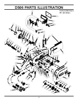
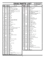
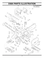
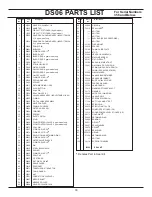
background image

30

DS06 PARTS LIST

For Serial Numbers 
356 and Below.

 Denotes Part in Seal Kit


 Item  Qty 

Part 

Description

   No 


No.


 Item  Qty 

Part 

Description

   No 


No.

 1  8 00753  HSHCS 

10-24UNCx1-1/4 

 2  1 33445  NAME 

TAG 

  3 

1  11207 

CIRCUIT "D" STICKER (8 gpm model)


1  11206 

CIRCUIT "C" STICKER (5 gpm model) 

  4 

1  07652 

REAR GEAR HOUSING ASSY (INCLD ITEM 5 &  


 6), 

gpm 

model 

only


1  07834 

REAR GEAR HOUSING ASSY (INCLD ITEM 5 &  


6), 5 gpm model only

 5  2 00289  DOWEL 

PIN 

 6  4 04041  BUSHING 

  7 

1  00020 

O-RING 5-329 R17 


 8  1 07612  IDLER 

SHAFT 

  9 

1  04105 

IDLER GEAR, 8 gpm model only


1  07831 

IDLER GEAR, 5 gpm model only 

 10 

1  32190  PIVOT PIN  

  11 

1  22716 

ST ELBOW 1/8NPT 

 12 

1  21550  WATER GAUGE  

  13 

1  04106 

DRIVE GEAR, 8 gpm model only


1  07832 

DRIVE GEAR, 5 gpm model only

 14 

1  32207  ON/OFF VALVE 

  15 

1  07626 

O-RING 2-014 R18  


 16 

2  07609  SPRING WASHER 

 17 

1  34119  SPRING 

  18 

1  04512 

RETAINING RING 1/2 EX 

 19 

1  07625  PLUG BUTTON 

 20 

2  03009  ROLL PIN 

 21 

1  07624  ROLL PIN-3/16 X 1 

  22 

1  32201 

VALVE HANDLE ASSY (INCLD ITEMS 31 & 66)

 23 

3  01605  O-RING 

 24 

2  01652  PIGTAIL HOSE ASSEMBLY 

 25 

1  24059  MALE COUPLER 

 26 

1  24058  FEMALE COUPLER 

 27 

1  33443  WATER HOSE ASSY 

 28 

1  34093  TRIGGER 

 29 

1  07602  SPRING 

 30 

1  34105  SAFETY CATCH 

 31 

1  32197  STUD 

  32 

1  33444 

FLOW CONTROL VALVE, 8 gpm model only


1  34006 

FLOW CONTROL VALVE, 5 gpm model only 

 33 

1  00072  ROLL PIN 

  34 

1  07627 

O-RING 2-016 R24 


 35 

1  00074  O-RING 2-021 R16 


  36 

1  33488 

SELF LOCKING RETAINING RING 

  37 

1  05632 

O-RING 2-005 R16 

 38 

1  33377  WATER VALVE SLEEVE 

 39 

1  01403  O-RING 2-020 R16 


 40 

1  33380  PIN 

  41 

1  36259 

STEEL BALL 3/8 DIA.  

  42 

1  32188 

SPRING   

 43 

1  04052  O-RING 3-914 R17 


 44 

1  32189  SEAL CAP 

 45 

1  28323  CE STICKER

  46 

1  06635 

RET RING 1 3/8 INT 

 47 

1  38898  SEAL SPACER 

 48 

1  32210  SPROCKET  

 49 

1  39071  TRANTORQUE™ ADAPTOR 

 50 

1  32255  CHAIN GUARD 

 51 

2  32203  NUT  

  52 

1  20721 

CORD STOCK 3/16DIA R1 

 53 

1  35897  MOTOR SHAFT 

 54 

1  04044  NEEDLE ROLLER 

 55 

1  02688  HSHCS 5/16-18UNCx3/4 

 56 

1  60804  O-RING 

 57 

1  19215  SEAL LINER 

 58 

-----  NO ITEM 

  59 

-----    NO ITEM

 60 

-----  NO ITEM

 61 


-----  SAW BAR (SEE ACCESSORIES) 

 62 

-----  NO ITEM

 63 

1  32196  FLAP MOUNT 

 64 

1  33219  SPACER 

 65 

1  32192  CHAIN GUIDE PLATE 

 66 

1  32245  STUD 

 67 

2  02446  HSHCS 1/4-20UNCx5/8 

 68 

1  02687  MACHINE SCREW 

 69 

1  32191  STAT-O-SEAL  


 70 

1  32198  BAR ADJUSTMENT NUT 

 71 

1  33481  WALLWALKER CLEVIS PIN 

  72 


SPRING (INCLD WITH ITEM 74) 

 73 


-----  CHAIN (SEE ACCESSORIES) 

 74 

1  32206  WALL WALKER 

  75 

1  02649 

HANDLE BAR RETAINER 

 76 

1  33229  HANDLE WELDMENT 

 77 

1  33260  BHCS 1/4-20x.625 ZINC 

 78 

1  33261  FENDER WASHER  

 79 

1  33258  HAND GUARD 

 80 

1  12412  WARNING STICKER-ELECT 

 81 

2  12175  WASHER 

 82 

2  33454  HHCS 5/16-18x5/8 ZINC 

 83 

1  33263  HANDLE GRIP  

 84 

1  33429  SPROCKET WRENCH 

  85 

1  17134 

NUT 1/4-20 HHD LT SST 

 86 

1

 31614  SPIROL 

PIN 

  87 

1  30635 

SPIROL PIN 5/16 x 7/8

 88 

1  28409  COMPOSITE STICKER (CE)

  89 

1  11212 

SOUND POWER LEVEL STICKER (CE)

 90 

1  00173  QUAD RING 

 91 

1  04856  RETAINING RING

 92 

1  35965  BEARING

 93 

1  00621  O-RING 

 94 

1  38897  SEAL WASHER

 95 

1  39070  V-RING

 96 

1  38700  SEAL RING

 97 

1 350810  O-RING 

 98 

1  07324  RETAINING RING

 99 

-----  NO ITEM

 100 1 

34118 SUPPORT 

WASHER

 33360 

SEAL 

KIT

Summary of Contents for DS06

Page 1: ...RATION AND MAINTENANCE SERVICE MANUAL WARNING Stanley Hydraulic Tools 3810 SE Naef Road Milwaukie OR 97267 5698 503 659 5660 FAX 503 652 1780 www stanley hydraulic tools com Copyright 2005 The Stanley Works OPS MAINT USA 34567 8 2005 Ver 3 ...

Page 2: ......

Page 3: ...MENTS 9 HTMA REQUIREMENTS 10 OPERATION 11 PREOPERTION PROCEDURES 11 CHECK THE POWER SOURCE 11 CHECK TOOL 11 CONNECT HYDRAULIC HOSES 11 CONNECTING TO A WATER SUPPLY 11 CHECK CHAIN AND BAR ADJUSTMENT 11 CHECK CHAIN SEGMENT WEAR 12 OPERATING PROCEDURES 12 PLAN THE CUT 12 TYPES OF CUTS 13 COLD WEATHER OPERATION 13 USING THE WALL WALKER 13 MAINTENANCE ADJUSTMENTS 14 GENERAL MAINTENANCE TIPS 14 SAW BAR ...

Page 4: ...ll 5 Year of manufacture Baujahr année de fabrication Año de fabricacion Anno di fabbricazione 1998 Has been manufactured in conformity with EEC Type examination as shown Wurde hergestellt in Übereinstimmung mit EEC Typ Prüfung nach Est fabriqué conformément au x type s examiné s comme indiqué dans le tableau ci après Ha sido fabricado de acuerdo con tipo examen EEC como dice E stata costruita in ...

Page 5: ...nel CAUTION WARNING DANGER NOTICE This is the safety alert symbol It is used to alert you to potential personal injury hazards Obey all safety messages that follow this symbol to avoid possible injury or death This safety alert and signal word indicate a potentially hazardous situation which if not avoided could result in death or serious injury This safety alert and signal word indicate a potenti...

Page 6: ...verreach Maintain proper footing and balnace at all times Do not inspect or clean the chain saw while the hydraulic power source is connected Accidental engagement of the chain saw can cause serious injury Always connect hoses to the chain saw hose couplers before engergizing the hydraulic power source Make sure all hose connections are tight Do not operate the chain saw at fluid temperatures above...

Page 7: ...and securely assembled Make sure the chain stops moving when the control trigger is released Keep the handle dry clean and free of hydraulic fluid Do not use the chain saw near energized transmission lines Turn off the power source or move the hydraulic control valve to neutral before setting the chain saw down Use a guide bar scabbard when transporting the chain saw Know the location of buried or ...

Page 8: ...O NOT LIFT OR CARRY TOOL BY THE HOSES DO NOT ABUSE HOSE DO NOT USE KINKED TORN OR DAMAGED HOSE 3 MAKE SURE HYDRAULIC HOSESARE PROPERLY CONNECTED TO THE TOOL BEFORE PRESSURING SYSTEM SYSTEM PRESSURE HOSE MUST ALWAYS BE CONNECTED TO TOOL IN PORT SYSTEM RETURN HOSE MUST ALWAYS BE CONNECTED TO TOOL OUT PORT REVERSING CONNEC TIONS MAY CAUSE REVERSE TOOL OPERATION WHICH CAN RESULT IN SEVERE PERSONAL INJ...

Page 9: ...SURE OR ABUSE HOSE IMPROPER USE OR HANDLING OF HOSE COULD RESULT IN BURST OR OTHER HOSE FAILURE KEEP HOSE AS FAR AWAY AS POSSIBLE FROM BODY AND DO NOT PERMIT DIRECT CONTACT DURING USE CONTACT AT THE BURST CAN CAUSE BODILY INJECTION AND SEVERE PERSONAL INJURY 4 HANDLE AND ROUTE HOSE CAREFULLY TO AVOID KINKING ABRASION CUTTING OR CONTACT WITH HIGH TEMPERATURE SURFACES DO NOT USE IF KINKED DO NOT USE...

Page 10: ...in service determine the most suitable temperature viscosity characteristics Hydraulic fluids with a viscosity index over 140 will meet the require ments over a wide range of operating temperatures SSU Saybolt Seconds Universal 4 6 gpm 7 9 gpm 11 13 gpm 9 10 5 gpm 15 23 lpm 26 34 lpm 42 49 lpm 34 40 lpm 2000 psi 2000 psi 2000 psi 2000 psi 138 bar 138 bar 138 bar 138 bar 2100 2250 psi 2100 2250 psi...

Page 11: ...on 2 Connect the hoses from the hydraulic power source to the chain saw fittings or quick disconnects It is a good practice to connect return hose first and disconnect them last to minimize or avoid trapped pressure within the chain saw 3 Observe the arrow on the couplers to ensure that the flow is in the proper direction The female coupler on the chain saw is the inlet pressure coupler NOTE If uncou...

Page 12: ...nce from the bottom of the bar See Check Chain Bar Adjustment in this manual 4 If the chain requires adjustment see Maintenance Adjustments in this manual PLAN THE CUT 1 Plan your cuts to prevent injury to yourself and to keep from pinching the saw bar and chain as a result of falling pieces of concrete brick etc 2 Make your cuts in the order shown in Figure 4 starting with cut 1 base horizontal c...

Page 13: ...draulic fluid at low power source speed When using the normally recommended fluids fluid should be at or above 50 F 10 C 400 ssu 82 centistokes before use Damage to the hydraulic system or chain saw can result from use with fluid that is too viscous or thick USING THE WALL WALKER The Wall Walker lessens operator fatigue and effort dur ing cutting by automatic insertion of the wedge into the cut thus a...

Page 14: ...from the groove at the bottom of the saw bar Figure 10 GENERAL MAINTENANCE TIPS Several simple maintenance tasks which if performed can keep a chain saw operating at a high level of efficiency Routine maintenance also keeps replacement costs down on the parts of the chain saw which occasionally wear out If any chain saw disassembly is required refer to the Ser vice Manual SAW BAR RAIL A quick check...

Page 15: ...a worn or damaged segment 1 Mount the chain breaker flush with the side or front of a flat clean work surface Figure 11 Figure 11 Chain Breaker Mounting Note The Stanley chain breaker is only designed to remove rivet heads from the connecting links not from a chain segment The rivet heads shown in the shaded areas of Figure 12 are the only ones that can be removed Figure 12 Removable Rivet Heads 2 P...

Page 16: ...ETS The following procedures explain how to spin rivets using Stanley s bench mounted rivet spinner part number 20857 to assembly the chain 1 Mount the rivet spinner flush with the side or front of a flat clean work surface Figure 17 Figure 17 Rivet Spinner Mounting 2 Lay the chain across the plastic chain supports and then rotate the supports so the rivet head is centered between the take up handle...

Page 17: ...NTENANCE ADJUSTMENTS Figure 23 Spinner Oiling Chambers NOTE the rivet spinner is equipped with oiling chambers and should be maintained periodically with a light weight oil Figure 23 NOSE SPROCKET DISASSEMBLY AND ASSEMBLY 1 Using the bench mounted chain breaker see acces sories line up the 1 4 inch hole in the side of the chain breaker anvil with the chain breaker punch Punch out the six nose spro...

Page 18: ...into the holes and then hold them with your thumb Remove the screwdriver and slide out the insertion card Note On used bars the nose rails might tend to spread apart Use a small clamp if necessary to hold the rails together 6 With the bar and rivets solidly supported on a strong flat steel surface carefully peen the rivet heads down with the flat end of a hammer Be careful to only hit the rivet head...

Page 19: ...use damage to internal seals Always replace hoses couplings and other parts with replacement parts recommended by Stanley Hydraulic Tools Supply hoses must have a minimum working pressure rating of 2500 psi 172 bar Do not exceed the rated flow see Specifications page in this manual for correct flow rate and model number Rapid failure of the internal seals may result Always keep critical tool markings...

Page 20: ... Should not exceed 250 psi 17 bar at 9 gpm 34 lpm measured at the end of the tools operating hoses Loss of diamond segment side clear ance Replace chain Chain segment dulled because of con tinuous use in hard material or rebar Redress segmented by cutting in abrasive material i e concrete build ing block etc Note This indicates that the wrong chain is being used Wrong chain for application Scale d...

Page 21: ... Blocked port s in bar Turn off hydraulic supply Remove bar and chain and clean bar thoroughly Blow ports with compressed air Blocked inlet or outlet Turn off hydraulic supply Remove bar and chain Make sure water supply is on Press trigger to see if water exits near bar adjustment nut area a small port If no water exits have unit serviced ...

Page 22: ... Hz 26237 HP1 Power Unit Water Pump Kit 29361 13 inch Bar Sprocket Nose 35037 Ultra 25 Diamond Chain for 13 inch Bar 56799 Pinnacle 25 Diamond Chain for 13 inch Bar 56800 Water Pump Attachment for GT18 HP1 with Couplers HWP10 Water Flow Meter 0 7 gpm 60859 SOUND POWER AND VIBRATION DECLARATION Measured A weighted sound power level Lwa ref 1pW in decibels 106 2 dBA Uncertainty Kwa in decibels 3 dBA...

Page 23: ...mage Some light surface scratches will be noticeable Grooves roughness or a reduced diameter indicate fluid contamination If abnormal wear is present more than normal polishing replace both the spool and the handle 2 Apply grease and install a new o ring 15 onto the ON OFF valve 14 3 Apply grease and install new o rings 34 35 into the spool bore of the handle 4 Apply grease and install new o rings ...

Page 24: ... to remove it and the seal washer 94 seal ring 96 v ring seal 95 o ring 93 and bear ing 92 from the front of the valve handle Remove the seal keeper seal spacer seal and o ring from the motor shaft 11 To remove the bearing from the shaft press on the out side end sprocket end of the motor shaft while supporting the outer race of the bearing Discard the old bearing 12 Remove the retaining ring 91 a...

Page 25: ... the seal liner Install the seal liner into the valve handle assy 22 Replace the retaining ring 91 3 To replace the bearing 92 onto the motor shaft 53 support the bearing inner race and press the motor shaft through the bearing inner race 4 Place the valve handle assy on a smooth clean arbor press surface protected from damage with the large bear ing bore facing up Position the valve handle so a c...

Page 26: ...over the Trantorque adapter cap 49 and then install this assembly onto the motor shaft While gripping the sprocket hand tighten the hex head of the Trantorque adapter cap by turning it clockwise 13 Slide the sprocket wrench 84 over the sprocket 48 While gripping the sprocket wrench and using an open end wrench tighten the hex head on the Trantorque adapter 49 clockwise to 17 lb ft 23 Nm BAR CHAIN ...

Page 27: ...27 DS06 PARTS ILLUSTRATION For Serial Numbers 357 and Above 54 99 ...

Page 28: ...32203 2 Nut 52 20721 1 Cord Stock 3 16 Dia 53 43690 1 Motor Shaft See Item 60 for Serial No Break 54 04044 2 Needle Roller 55 02688 1 HSHCS 5 16 18 UNC x 3 4 Item No Part No Qty Description 56 60804 1 O Ring 57 19215 1 Seal Back Up Washer 58 43689 1 Sprocket Adapter 59 58969 1 Wiper Seal 60 41763 1 E Clip For DS063000 s n 434 and below and for DS06200001 s n 110 and below 66299 1 Spiral Retainer R...

Page 29: ...29 DS06 PARTS ILLUSTRATION For Serial Numbers 356 and Below ...

Page 30: ...37 1 05632 O RING 2 005 R16 38 1 33377 WATER VALVE SLEEVE 39 1 01403 O RING 2 020 R16 40 1 33380 PIN 41 1 36259 STEEL BALL 3 8 DIA 42 1 32188 SPRING 43 1 04052 O RING 3 914 R17 44 1 32189 SEAL CAP 45 1 28323 CE STICKER 46 1 06635 RET RING 1 3 8 INT 47 1 38898 SEAL SPACER 48 1 32210 SPROCKET 49 1 39071 TRANTORQUE ADAPTOR 50 1 32255 CHAIN GUARD 51 2 32203 NUT 52 1 20721 CORD STOCK 3 16DIA R1 53 1 35...

Page 31: ...hard aggre gate concretes granite quartz river rock etc Moderate steel rein forcing wire mesh 3 8 1 2 inch 10 12 mm diameter Soft aggregate concrete concrete block masonry green concrete highly abrasive 13 inch Medium hard aggregate concretes granite quartz river rock etc Moderate steel reinforcing wire mesh 3 8 1 2 inch 10 12 mm di ameter Soft aggregate concrete concrete block masonry green concr...

Page 32: ... DAMAGES To the fullest extent permitted by applicable law in no event will STANLEY be liable for any incidental consequential or special damages and or expenses FREIGHT DAMAGE Damage caused by improper storage or freight handling LOSS TIME Loss of operating time to the user while the tool s is out of service IMPROPER OPERATION Any failure or performance deficiency attributable to a failure to foll...

Page 33: ...Stanley Hydraulic Tools 3810 SE Naef Road Milwaukie OR 97267 5698 503 659 5660 FAX 503 652 1780 www stanley hydraulic tools com ...

Reviews: