Stanley BR87 User Manual Download Page 11

BR87 User

 Manual ◄ 11

NOTE: 
Partially depressing the trigger allows the tool to run 

at slow speed. Slow-speed operation permits easier 

starting of the tool bit into the work surface.

5.  To start, break an opening (hole) in the center of the 

surface. After making a hole, break portions of the 

material into the original opening. For best produc-

tivity, the breaking should be done around the origi-

nal hole. 
The size of the broken material will vary with the 

strength and thickness of the base material and the 

amount of any reinforcement wire or rebar.
Harder material or more reinforcing wire or rebar will 

require taking smaller bites. To determine the most 

effective bite, start with 2 in. / 50 mm or smaller bites.
Bites can then be gradually increased until the bro-

ken piece becomes too large, requiring increased 

time to break off the piece.
Sticking of the tool bit occurs when too large a bite is 

being taken and the tool bit hammers into the mate-

rial without the material fracturing. This causes the 

tool bit to become trapped in the surrounding mate-

rial.

6.  The underwater model requires preventative main-

tenance after each day’s use underwater and prior 

to being placed in storage. See the General Service 

Notes section in this manual for this maintenance 

procedure.

COLD WEATHER OPERATION

If the breaker is to be used during cold weather, preheat 

the hydraulic fluid at low engine speed. When using the 

normally  recommended  fluid,  fluid  temperature  should 

be at or above 50 °F/10 °C (400 ssu/82 centistokes) be-

fore use.
Damage to the hydraulic system or breaker can result 

from use with fluid that is too viscous or thick.

The recommended hose size is .500 inch/12 mm I.D. up 

to 50 ft/15 m long and .625 inch/16 mm I.D. minimum up 

to 100 ft/30 m.

PRE-OPERATION PROCEDURES

CHECK POWER SOURCE

1. 

Using a calibrated flowmeter and pressure gauge, 

check that the hydraulic power source develops a 

flow  of  7-9  gpm/26-34  lpm  at  1500-2000  psi/105-

140 bar.

2.  Make certain the hydraulic power source is equipped 

with a relief valve set to open at 2100-2250 psi/145-

155 bar maximum.

INSTALL TOOL BIT

1.  Rotate the latch on the breaker foot downward 

(pointing away from the tool).

2.  Insert the tool bit into the foot and pull the latch up to 

lock the tool bit in place.

CONNECT HOSES

1.  Wipe all hose couplers with a clean, lint-free cloth 

before making connections.

2.  Connect the hoses from the hydraulic power source 

to the tool fittings or quick disconnects. It is a good 

practice  to  connect  return  hoses  first  and  discon

-

nect them last to minimize or avoid trapped pressure 

within the tool.

3. 

Observe flow indicators stamped on hose couplers 

to  ensure  that  fluid  flow  is  in  the  proper  direction. 

The female coupler on the tool hose is the inlet cou-

pler.

4.  Move the hydraulic circuit control valve to the ON 

position to operate the tool.

NOTE:
If uncoupled hoses are left in the sun, pressure in-

crease within the hoses may make them difficult to 

connect. When possible, connect the free ends of 

the hoses together.

OPERATION PROCEDURES

1.  Observe all safety precautions.
2.  Install the appropriate tool bit for the job.
3. 

Place the bit firmly on the surface to be broken.

4.  Squeeze the trigger to start the breaker. Adequate 

down pressure is very important. When the tool bit 

breaks through the obstruction or becomes bound, 

release the trigger and reposition the tool bit.

OPERATION

Summary of Contents for BR87

Page 1: ...2014 Stanley Black Decker Inc New Britain CT 06053 U S A 65778 6 2015 Ver 15 USER MANUAL Safety Operation and Maintenance BR87 HYDRAULIC BREAKER...

Page 2: ...38 kg Has been manufactured in conformity with Wurde hergestellt in bereinstimmung mit Est fabriqu conform ment Ha sido fabricado de acuerdo con E stata costruita in conformit con Directive Standards...

Page 3: ...ds that servicing of hydraulic tools other than routine maintenance must be performed by an authorized and certified dealer Please read the following warning For the nearest authorized and certified d...

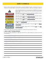
Page 4: ...is symbol to avoid possible injury or death DANGER This safety alert and signal word indicate an imminently hazardous situation which if not avoided will result in death or serious injury WARNING This...

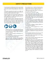
Page 5: ...00 psi 175 bar Be sure all hose connections are tight The hydraulic circuit control valve must be in the OFF position when coupling or uncoupling the tool Wipe all couplers clean before connecting Use...

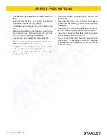
Page 6: ...e observant of the hydraulic hoses lying about the work area they can be a tripping hazard Always de energize the hydraulic system when changing a tool bit Take caution when changing a tool bit tool b...

Page 7: ...CTORS DAILY FOR LEAKS DO NOT FEEL FOR LEAKS WITH YOUR HANDS CONTACT WITH A LEAK MAY RESULT IN SEVERE PERSONAL INJURY I M P O R T A N T D DO NOT LIFT OR CARRY TOOL BY THE HOSES DO NOT ABUSE HOSE DO NOT...

Page 8: ...SORBENT CLOTH TO REMOVE DIRT AND MOISTURE AND TEST HOSE FOR MAXIMUM ALLOWABLE CURRENT LEAKAGE IN ACCORDANCE WITH SAFETY DEPARTMENT INSTRUCTIONS SEE OTHER SIDE SIDE 2 D O N O T R E M O V E T H I S T A...

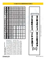
Page 9: ...4 Return 2500 175 13 16 49 60 up to 25 up to 8 5 8 16 Pressure 2500 175 3 4 19 Return 2500 175 13 16 49 60 26 100 8 30 3 4 19 Pressure 2500 175 1 25 4 Return 2500 175 Figure 1 Typical Hose Connections...

Page 10: ...13 gpm 15 23 lpm 26 34 lpm 34 40 lpm 42 49 lpm 1500 psi 1500 psi 1500 psi 1500 psi 103 bar 103 bar 103 bar 103 bar 2100 2250 psi 2100 2250 psi 2200 2300 psi 2100 2250 psi 145 155 bar 145 155 bar 152...

Page 11: ...se with fluid that is too viscous or thick The recommended hose size is 500 inch 12 mm I D up to 50 ft 15 m long and 625 inch 16 mm I D minimum up to 100 ft 30 m PRE OPERATION PROCEDURES CHECK POWER S...

Page 12: ...sure rating of 2500 psi 172 bar Do not exceed the rated flow and pressure See Specifications in this manual for correct flow rate and pressure rating Rapid failure of the internal seals may result Alw...

Page 13: ...er unit for proper flow 7 9 gpm 26 34 lpm High backpressure Check hydraulic system for excessive backpressure over 250 psi 17 bar Couplers or hoses blocked Remove restriction Orifice plug blocked Remo...

Page 14: ...rging valve Be careful not to overtighten Install the protective cap and valve cap assembly ACCUMULATOR CHARGING 1 Perform steps 1 through 4 of the accumulator test ing procedure above 2 Connect the c...

Page 15: ...er and debris as follows 1 Turn the tool upside down without the tool bit and spray oil through the drive hex and side holes in the breaker foot assembly to displace any remaining water in the lower p...

Page 16: ...Pa at operator s position in decibels 102 dBA Uncertainty Kpa in decibels 3 dBA Values determined according to noise test code given in ISO 15744 using the basic standard ISO3744 Test conducted by in...

Page 17: ...ng UC 04404 Clay Spade 8 in 20 cm Blade 04405 Asphalt Wedge 08119 Clay Spade 5 1 2 in Blade 09262 TEST EQUIPMENT Accumulator Tester 02835 Flow and Pressure Tester 04182 Accumulator Charge Kit Includes...

Page 18: ...anual BR87 PARTS ILLUSTRATION 47 35 14 11 34 10 13 12 9 23 19 20 65 18 17 66 63 OIL IN 25 3 15 7 16 64 7 28 26 8 21 61 30 40 24 44 43 42 44 41 46 36 5 58 6 57 4 2 60 22 45 7 38 39 46 33 32 27 31 67 29...

Page 19: ...BR87 User Manual 19 BR87 PARTS ILLUSTRATION...

Page 20: ...04983 1 BOLT 42 01744 1 SPRING 43 01745 08411 1 DETENT 1 000 OAL SERIAL NO 1707 AND BELOW DETENT 1 250 OAL SERIAL NO 1708 AND ABOVE Item No Part No Qty Description 44 01269 2 RUBBER SLEEVE 1 000 45 0...

Page 21: ...e hydraulic tools at depths of thousands of feet ROV operation is still limited to the tool for example a percussive tool has the same depth limitation whether ROV or diver operated UNDERWATER TOOLS D...

Page 22: ...Stanley Hydraulic Tools 3810 SE Naef Road Milwaukie Oregon 97267 5698 USA 503 659 5660 Fax 503 652 1780 www stanleyhydraulics com...

Reviews: