Stanford Pupper 2.1 Assembly And Operation Manual Download Page 6

Electronics

1. Wiring the bottom PCB

1. Solder the XT-60 leads.
2. Mount the Teensy to the bottom PCB in the indicated orientation.
3. Insert the ends of the power switch wires into the screw terminals on the bottom

PCB. There are labels on the PCB indicating which color wire goes where.

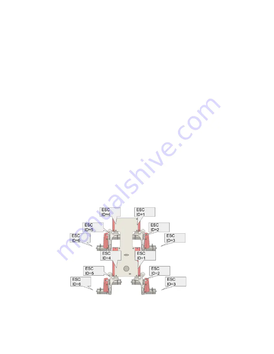
2. Set motor controller IDs

Each C610 motor controller needs an ID number so that it knows which motor commands
to listen to. The front and back motor controllers are on separate CAN networks so their
IDs can overlap, but on each network, each controller must have a unique ID.

Review the diagram below to see which motor controllers have what ID.

Setting the ID

1. Press the C610 button once to tell it to enter ID-setting mode
2. Without pausing (aka within 1s), press the button additional times, with the number

of presses indicating the ID. For example, press it once to put it into ID-setting
mode, then press the button 6 more times to assign it the ID number 6. After each
of the presses after the first press to change the mode, you should see the blue light
flash.

3. The C610 will now reboot and the number of green flashes indicates the ID. After

the flashing sequence is complete, it’ll wait a little and repeat the sequence.

Summary of Contents for Pupper 2.1

Page 1: ...Stanford Pupper 2 1 Assembly and Operation...

Page 2: ...es Steps to complete before following the build video Changes to video instructions Setting motor controller IDs Calibrating motors Reference diagrams for screw sizes review before watching video Buil...

Page 3: ...ated need to upload latest files A readme is included in this folder for fabrication instructions Videos for purchasing the pcbs Teensy shield https www youtube com watch v Jm57xkEqToU Bottom PCB http...

Page 4: ...ft and right side are correspondingly embossed with an L or R The embossed triangles indicate the correct direction of the motor wires The following image shows a cross section of a correctly inserted...

Page 5: ...all M3x6 flat head cap screws used to mount the motors This is mandatory as otherwise these screws will quickly loosen from repeated foot ground impacts Melt the cut ends of the cable sleeving to pre...

Page 6: ...on each network each controller must have a unique ID Review the diagram below to see which motor controllers have what ID Setting the ID 1 Press the C610 button once to tell it to enter ID setting m...

Page 7: ...ttached legs Steps 1 Long press the C610 button to enter calibration mode release once it starts beeping 2 The motor will now slowly turn to calibrate itself 3 The controller will reboot once finished...

Page 8: ...dowel pin 91585A379 1 M2 5 hex nut 91828A113 1 Motor DJI M2006 1 Motor driver DJI C610 1 Cable sleeving 20cm length 3D printed parts 1 Upper leg 1 Upper leg cover Instructions Upper Leg All Steps mp4...

Page 9: ...6 M3x6 flat head cap screw 92125A126 4 M3x16 dowel pin 91585A379 2 Motor DJI M2006 2 Motor driver DJI C610 3D printed parts 1 Motor bulkhead Instructions Motor Bulkhead All Steps mp4...

Page 10: ...Descr ID 2 M2 5x16 shoulder screw 90265A420 4 Zip tie Subassemblies 1 Leg L 1 Leg R Instructions Todo add video 3 Pupper Quantity to assemble 1 Parts Qty Descr ID 16 M3x6 button head cap screw 92125A1...

Page 11: ...by Tom Stewart g Linux only i Download the following file https www pjrc com teensy 00 teensy rules and put it under etc udev rules d ii Reload udev rules sudo udevadm control reload rules udevadm tr...

Page 12: ...It will immediately begin the homing sequence 1 6 Wait 20 seconds for the Raspberry Pi to boot up 1 7 The robot is now ready to receive control inputs 2 Controls Transmitter Input Function Left thumbs...

Page 13: ...mbsticks facing away from the robot 5 Charging 5 1 Remove the left side cover 5 2 Unplug the battery s XT 60 and JST XH connectors 5 3 Charge the battery with a 6S lithium ion balance charger More inf...

Page 14: ...Reference Actuator Numbering...

Reviews: