Standen Unistar 2400 Operator'S Handbook Manual Download Page 14

minimum1/2 overlap 


PTO Shaft 

The machine is designed to operate with the tractors 540 rpm, 6 spline, 1 3/8” PTO 
output shaft. 


PTO  speeds  greater  than  540  rpm  will  cause  damage  to  the  system 
and if exceeded may invalidate the warranty. 


Fit the two halves of the PTO shaft onto their respective drive shafts on the machine 
and tractor. Check the shaft length by turning the tractor fully in both directions with 
the  machine  in  its  working  position  while  attached  to  the  tractor’s  pick-up  hitch. 
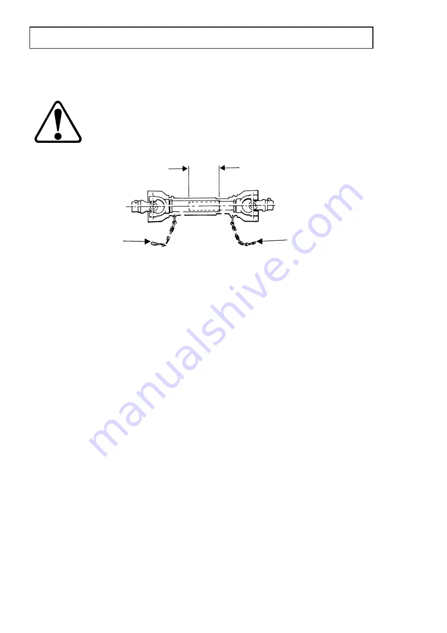
Ensure  the  sliding  tubes,  when  fully  extended,  have  an  overlap  at  least  half  the 
closed  length  (see  figure  3).  Ensure  that  the  ends  of  the  sliding  tubes  when  at  the 
shortest  point  are  not  in  contact  with  other  parts  of  the  PTO  shaft.  If  necessary, 
shorten  both  tubes  and  guards  equally  to  achieve  end  clearance  at  the  minimum 
length position. 
 
Make sure that the drive shaft is fitted correctly and that the lock pins are engaged. 
 
All  the  parts  of  the  PTO  shaft,  especially  the  guards,  must  be  kept  in  good  order. 
Check  regularly  that  the  guard  is  undamaged  and  fully  protects  the  whole  of  the 
shaft, and that both the guard and the shaft will telescope freely. 
 
If  it  is  possible  to  engage  the  inner  and  outer  parts  of  a  drive  in  more  than  two 
positions circumferentially then make sure that the universal joint yokes are correctly 
aligned. 
 
Check that when in the continuous working position, the drive shaft is not at an angle 
of  more  than  20°  from  the  PTO  centre  line.  The  angle  between  the  drive  shaft  and 
the input and output shafts should be equal. 
 
Ensure that the safety chains (item 1, fig 3) used to prevent the guards from turning, 
are  fixed  to  the  tractor  and implement  in  such  a  way  that  they  will  not  be  stretched 
when the drive shaft is at maximum articulation. When disconnected from the tractor, 
position the PTO shaft on the drawbar PTO rest as shown in figure 1. 


1.9   


                         INSTALLATION 

Fig 3 

Summary of Contents for Unistar 2400

Page 1: ...Unistar 2400 Soil Separator Standen Engineering Limited Hereward Works Station Road Ely Cambridgeshire CB7 4BP England Tel 01353 661111 www standen co uk Fax 01353 662370 ...

Page 2: ......

Page 3: ...e CB7 4BP This handbook is issued on the condition that it must not be used copied or exhibited without their written permission IMPORTANT This operator s handbook should be regarded as part of the machine Suppliers of both new and second hand machines are advised to retain documentary evidence that this handbook was supplied along with the machine On installation of the machine i e starting off i...

Page 4: ......

Page 5: ...matic Depth Control 1 14 Setting the Automatic Depth Control 1 14 Discs 1 16 Shares 1 16 Underweb 1 16 Boulder Box 1 17 Cross Conveyor 1 17 Braked Axles 1 18 Actiflow Star Spacing 1 18 Vari Flow Web 1 18 MAINTENANCE Lubrication 1 19 Drive Belt Maintenance 1 20 Electrical System Maintenance 1 20 Hydraulic System Maintenance 1 20 Residual Hydraulic Pressure Dump Procedure 1 21 Star Shaft Removal 1 2...

Page 6: ...amage to the machine and carefully read the message that follows Throughout this handbook the terms front rear left hand LH and right hand RH are derived from the tractor driver s position facing forward in the normal direction of travel Adjustments to the machine may have to be made singly or in combination according soil conditions Always allow the machine to settle to a new setting before makin...

Page 7: ...onents or even complete assemblies are redesigned from time to time Where possible the modifications are shown in the remarks column The first printing of each page in the spare parts section is identified as issue 1 at the foot of the page When a complete unit or assembly has been redesigned the appropriate pages are revised and printed as issue 2 The revised pages are filed behind the existing i...

Page 8: ...yone in the vicinity is aware of your intentions Never allow children or animals in the vicinity where machines are working and never allow anyone to ride on the machine In dry dusty conditions it is prudent to use a tractor with an enclosed cab Never attempt to fit drive chains or drive belts to the machine while the drive sprockets or pulleys are in motion Normal safe working procedures should b...

Page 9: ...cularly those securing the rotor blades tines Always use mechanical or additional help when lifting heavy parts Regularly check hydraulic hoses for chafing or damage and replace as necessary Care must be taken when carrying out any work on the hydraulic system Even when stopped and disconnected from the tractor residual pressure will exist within the hydraulic system Therefore before commencing an...

Page 10: ...1 5 SAFETY PRECAUTIONS ...

Page 11: ...SAFETY PRECAUTIONS 1 6 ...

Page 12: ... a wheel place a stout support under the tractor frame in case the jack should become dislodged Drawbar The drawbar is designed to be attached to the tractor pick up hitch The jack stand item 1 fig 1 is provided so that the machine is held at a suitable height for safe coupling to the tractor Always ensure the stand is positioned on firm level ground to avoid the machine sinking or sliding whilst ...

Page 13: ... valve item 3 fig 2 Open the tractor spool valve while closely watching the pressure gauge item 4 fig 2 When the pressure reaches 65 bar immediately close the spool valve and then close the accumulator valve If necessary reduce the pressure slightly using the accumulator valve The drawbar is now pressurised and ready for operation If in work due to differing soil conditions the initial setting of ...

Page 14: ...hat the drive shaft is fitted correctly and that the lock pins are engaged All the parts of the PTO shaft especially the guards must be kept in good order Check regularly that the guard is undamaged and fully protects the whole of the shaft and that both the guard and the shaft will telescope freely If it is possible to engage the inner and outer parts of a drive in more than two positions circumf...

Page 15: ...tanden dealer There must no restriction in this return oil Ensure that there is a full flow return or even better return straight back into the tractor gearbox Consult your tractor handbook or dealer for further information Open Closed Centre Hydraulics Two types of hydraulic system are currently in use by tractor manufacturers namely OPEN CENTRE or CLOSED CENTRE configurations Consult the tractor...

Page 16: ...lic drawbar push button activates deactivates the hydraulically damped drawbar system The LED is illuminated when the system is switched on Digger Share Raise Lower The 3 position spring toggle switch manually raises lowers the digger assembly increasing decreasing the depth of the shares below the soil Releasing the switch to the central position leaves the share depth at the present setting Sett...

Page 17: ...eb to discharge to the LH or RH side of the machine With the switch in the centre position the discharge web is stopped Move the switch up to discharge to the RH side of the machine or down to discharge to the LH side The corresponding LED will illuminate The dial marked cross conveyor speed control sets the speed of the discharge web Turn the dial clockwise to increase or anticlockwise to decreas...

Page 18: ...is important that the machine is correctly fitted to the tractor and that the tractor handbrake is applied whilst axle adjustments are made Place chocks at the front and rear of the opposite side wheel to the one being adjusted Jack up the machine and place an axle stands under the chassis and lower the jack to allow the axle stands to take the weight of the machine Release the track rod locking b...

Page 19: ...e machine in work so that the relative working position of the roller and shares is correct 1 Release the front and rear quadrant stops item 4 5 fig 8 on both sides of the roller unit 2 Lower the machine into work until the shares are at the required digging depth 3 Slide the front stops item 4 fig 8 up against front edge of the quadrant arms item 6 fig 8 and lightly secure 4 Raise the machine sli...

Page 20: ...The LED will illuminate when the system is activated 4 Turn the depth control dial until the depth indicator aligns with the noted reading 5 Note the reading on the control box display highlighted AUTO DEPTH SENSOR ANALOG This figure together with the reading on the depth indicator will represent the initial depth setting To increase the depth turn the depth control dial clockwise To decrease the ...

Page 21: ...retighten Shares The standard machine is fitted with a 11 piece share blade arrangement The outside blades come in two different widths standard and wide to cope with the variety of bed widths In general the standard outer blade is fitted for the narrower bed widths while the wide outer blade is fitted for the wider bed widths If blade widths are altered then the disc positions will have to be adj...

Page 22: ...tors one at each end In order to place the conveyed material into the centre of the designated trench the speed of the cross web must be coordinated with the amount of traverse The LH side of the cross conveyor item 1 fig 12 can be folded vertically to reduce the width for transport and storage To unfold the cross conveyor 1 Remove the R clip item 2 fig 12 securing the transport lock top link item...

Page 23: ...n different conditions by using variations in forward and rotational speeds Only general advice can be given with regard to star spacing as any settings must be governed by soil and weather conditions Your authorised STANDEN ENGINEERING LTD dealer will be pleased to discuss and give recommendations and assistance on the best set up to suit your requirements Section 3 of this handbook contains diag...

Page 24: ... signs of leaks and checked for oil level and if necessary topped up The gearbox uses BP EP HYPO ENERGEAR 85W 140 To ensure the efficient operation of the PTO shafts it is vital to grease the sliding section on a daily basis Failure to do this will result in early failure of the shafts The PTO shaft should be disconnected from the tractor and the two halves pulled completely apart Each half should...

Page 25: ... The components within the hydraulic circuit are designed on the whole to be maintenance free If it becomes necessary to carry out any repair the work should be carried out by a competent engineer capable of this type of work WARNING Do not carry out any maintenance or release any hoses without first carrying out the residual hydraulic pressure dump procedure outlined later in this section Cleanli...

Page 26: ... disconnect the machine from the tractor leaving the hydraulic and electrical connection still attached 3 Move the tractor forward so that the machine drawbar is just clear of the tractor hook 4 Operate the machine levelling rams until the machine is in its lowest position 5 Switch off the tractor engine 6 Operate all switches on the driver s control box in turn to remove any remaining pressure wi...

Page 27: ...should be adjusted as close as possible without actually touching 6 Check all hydraulic cylinders valves and pipe work for signs of leaks or damage repair or replace as necessary 7 Carry out lubrication 8 Grease axle king pins Weekly Maintenance During the working season the following weekly maintenance should be carried out 1 Carry out all the procedures listed in daily maintenance 2 Check all sh...

Page 28: ...ent on any exposed bright metal surfaces which have been polished by the soil flow 2 Clean all drive belts 3 After carrying out the hydraulic residual pressure dump procedure any parts of hydraulic cylinders rods that are still exposed should be greased or oiled to prevent corrosion 4 Ensure that the tyres are inflated to the correct pressure 5 Ensure that the hydraulic hose quick release coupling...

Page 29: ...ractor 12V DC negative earth Drive requirement from tractor PTO 1 3 8 6 spline 540 rpm maximum Tyre size standard 12 5 x 20 MPT 10 Ply Tyre pressure 3 5 Bar 51 psi Wheel nut torque M20 x 1 5 360 nm Nut bolt torque Description Torque Description Torque M6 nyloc zinc nut 14 nm M6 bolt steel nut 10 nm M8 nyloc zinc nut 31 nm M8 bolt steel nut 26 nm M10 nyloc zinc nut 60 nm M10 bolt steel nut 52 nm M1...

Reviews: