


17
6.3- Assembling the Pump
6.3.1- Getting Prepared for Mounting
• It must be ensured that the parts to be used are clean before starting mounting. Clean the oil, dirt
on the parts with a solvent.
• The impeller and the body must be inspected for wear, fraction and breakdown.
• Replacement is necessary if the radial clearances between the impeller and the volute casing
1 mm.
• It must be ensured that the surfaces of the O-ring and/or bolts are clean.
6.3.2- Mounting
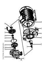
The mounting procedure is the reverse of the demounting procedure. Exploded view or cross sectional
view can be referenced during mounting.
• Put the shaft (060) on the electric motor (600). Don’t tighten the set screw (380) completely.
• If rigid coupling is used, put the rigid coupling (085) on the electric motor (600) shaft.
• In sequence, put allien screw and washer (340), shaft (060) with screws (320).
• Put the thrower (088) on the shaft.
• Assemble the motor pedestal (005) on the electric motor (600).
• Put the mechanical seal cover (043) on the motor pedestal (005).
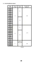
• According to pump group, arrange S value
(see table 5)
tighten the set screw (380) completely on
the shaft.
• First put the stationary part of mechanical seal (405) and after that put the rotationary part.
• Put the mechanical seal spacer sleeve (049) on the shaft (060).
• Attach the impeller key (210).
• Insert the impeller (050) and tighten the impeller nut (065).
Be careful with processed surfaces. The defects on the processed surfaces may cause
permanent damages.
ATTENTION
S
Figure 9.
Mounting the pump shaft on the electric motor shaft


