


11
Isolation Valve
Vent Valve
Figure 3
4.4.4- Auxiliary pipe connections and accessories
• Depending on the application auxiliary pipe connections (for
cooling, sealing and flushing of seal, drainage etc. necessary for
the pumping system) and/or accessories to check operating
conditions (pressure gauges, temperature gauges etc.) may be
made up and lail.
• Pressure and vacuum gauges must be properly anchored and
connected at the measuring points located on the pump flanges
by means of or on the pipes close to the flanges approximately
8 mm diameter tubing with pig tail configuration to lessen
pressure fluctuation. For safety purposes isolating and vent valves
should be fitted before the gauges
(Figure 3)
.
• Every pump is fitted with connections on the pump casing to
drain the pump
(Figure 4)
. If required the pump drain can be piped
to a suitable reservoir. The pump draining piping must be fitted
with an isolating valve and both must be suitable for the
maximum operating pressure of the pump.
• Cooling, sealing and flushing of seal piping must be connected
only to the designated connections located on the pump
(Figure 5,6).
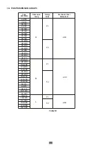
d1 :
Pressure gauge (discharge)
d2 :
Pressure gauge (suction)
d3 :
Filling or vent
d4 :
Drain
Figure 4
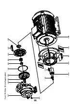
Figure 6
Figure 5
d3
d1
d4
d2
F1
F1 Q1
Q2
F1 :
Seal flushing liquid inlet from external source
Q1:
Mechanical seal quench liquid inlet from external source.
Q2:
Mechanical seal quench liquid outlet.


