background image

Page 73

HX851E

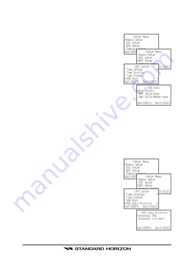
10.8 SOG UNIT

Allows the SOG shown on the NAV display to be shown in Kts (knot), MPH
(mile/hour) or KPH (kilo-meter/hour). The default setting is “Kts: Knots”.

1. Press and hold the [

CALL

(

ENT

)

MENU

] key un-

til “

Setup Menu

” appears.

2. Press the [

] key to select “

GPS Setup

” menu.

3. Press the [

CALL

(

ENT

)

MENU

] key, then select

SOG Unit

” in the “

GPS Setup

” menu with the [

] / [

]

key.

4. Press the [

CALL

(

ENT

)

MENU

] key.

5. Press the [

] / [

] key to select the desired unit.

6. Press the [

CALL

(

ENT

)

MENU

] key to store the

selected setting.

7. To exit this menu and return to radio operation mode

press the [

16/9

] key or press the [

CLR

] key several

times.

10.9 POS DATA PRIORITY

This menu item allows the 

HX851E

 to:

a. use the internal GPS to compute and display position information (de-

fault setting)

b. use the NMEA output of an external GPS Chart Plotter to input position

information into the 

HX851E

. This is a useful feature when the 

HX851E

is located in an area where GPS reception is limited and this selection
increases battery life of the 

HX851E

 between charges.

1. Press and hold the [

CALL

(

ENT

)

MENU

] key un-

til “

Setup Menu

” appears.

2. Press the [

] key to select “

GPS Setup

” menu.

3. Press the [

CALL

(

ENT

)

MENU

] key, then select

POS DATA Priority

” in the “

GPS Setup

” menu with the

[

] / [

] key.

4. Press the [

CALL

(

ENT

)

MENU

] key.

5. Press the [

] / [

] key to select “

Internal GPS

or “

External I

/

O port

”.

6. Press the [

CALL

(

ENT

)

MENU

] key to store the selected

setting.

7. To exit this menu and return to radio operation mode

press the [

16/9

] key or press the [

CLR

] key several

times.

Summary of Contents for HX851E

Page 1: ...Page 1 HX851E HX851E Floating Marine Transceiver with GPS Owner s Manual ...

Page 2: ...ITIAL SETUP 22 6 3 RECEPTION 22 6 4 TRANSMISSION 23 6 5 DISPLAY MODE SETUP 24 6 6 INTERNATIONAL USA AND CANADA CHANNELS 25 6 7 SIMPLEX DUPLEX CHANNEL USE 25 6 8 SCANNING 26 6 9 DUAL WATCH 28 6 10 PRESET CHANNELS 0 9 INSTANT ACCESS 28 6 11 STROBE OPERATION 29 7 DIGITAL SELECTIVE CALLING 30 7 1 GENERAL 30 7 2 MARITIME MOBILE SERVICE IDENTITY MMSI 30 7 3 DSC DISTRESS ALERT 32 7 4 ALL SHIPS CALL 36 7 ...

Page 3: ...2 STORING WAYPOINTS 77 12 3 EDITING A WAYPOINT 78 12 4 DELETING A WAYPOINT 78 12 5 SAVING A DSC POSITION CALL AS A WAYPOINT 79 12 6 NAVIGATING TO A SAVED WAYPOINT 80 12 7 STOP NAVIGATING TO A WAYPOINT 80 12 8 WAYPOINT SETUP 81 13 ATIS SETUP 82 13 1 ATIS CH GROUP 82 13 2 ATIS CODE PROGRAMMING 83 14 MAINTENANCE 84 14 1 GENERAL 84 14 2 REPLACEMENT PARTS 84 14 3 TROUBLESHOOTING CHART 85 15 CHANNEL ASS...

Page 4: ... the radio on or off BUTTONS Selects the operating channel Adjusts the audio volume level Adjusts the squelch threshold level Selects the item in the DSC Call Menu and Setup Menu TRANSMISSION SWITCH S p e a k i n t o t h e microphone in a normal voice level while pressing this switch MIC When transmitting position your mouth about 1 2 2 5 cm away from the small mic hole Speak slowly and c l e a r ...

Page 5: ...ating channel Triple Watch CALL ENT MENU BUTTON Press to access the DSC MENU Press and hold to access the Radio and DSC setup menus When DSC Call Menu or Setup Menu are selected pressing this key saves a selection CLR BUTTON Press to cancel the menu selection PRESET BUTTON Press to recall the Preset channel Press and hold to save the current channel into the Preset Memory ...

Page 6: ...nual thoroughly so as to learn and fully understand the capabilities of the HX851E Technical support information and assistance can be obtained in Eu rope from our Website www standardhorizon co uk NOTE Water resistance of the transceiver is assured only when the battery pack is attached to the transceiver and MIC SP cap is installed in the MIC SP jack This transceiver works on frequencies which a...

Page 7: ...851E transmitter provides a full 6 Watt of transmit power and is select able to 5 2 5 and 1 Watt to assist the user in ensuring maximum battery life The HX851E has the capability of Digital selective Calling with Distress call including GPS position All Ship Urgency and Safety Individual Group and Position Request and Position Report calls In addition the HX851E has navigation features which inclu...

Page 8: ... 73A4B Speaker Microphone MH 57A4B Mini Speaker Micro phone VC 24 VOX Headset VC 27 Earpiece Micro phone CN 3 Radio to Ship s An tenna Adapter CD 38 Charger Cradle FNB V99LI 7 4 V 1150 mAh Li Ion Battery Pack FBA 38 Alkaline Battery Case NC 88C U Wall Charger for the FNB V99LI C suffix is for use with 230 VAC Type C plug and U suffix is for use with 230 VAC Type BF plug Note Before operating the H...

Page 9: ...F Marine channel assignments refer to page 88 section 15 3 2 EMERGENCY CHANNEL 16 USE Channel 16 is known as the Hail and Distress Channel An emergency may be defined as a threat to life or property In such instances be sure the trans ceiver is on and set to CHANNEL 16 Then use the following procedure 1 Press the PTT Push To Talk switch on the left side of the transceiver and say Mayday Mayday May...

Page 10: ...initial contact When the hailing channel 16 is clear state the name of the other vessel you wish to call and then this is followed by the name of your vessel and your Station License Call Sign When the other vessel returns your call immedi ately request another channel by saying go to the number of the other chan nel and over Then switch to the new channel When the new channel is not busy call the...

Page 11: ...osure compliance require ments to be exceeded The radio is transmitting when the red LED on the front panel of the radio is illuminated You can cause the radio to transmit by pressing the PTT button or by using the VOX headset if the radio is supported Always use the Vertex Standard authorized Battery Pack Risk of explosion if battery is replaced by an incorrect type Dispose of used batteries acco...

Page 12: ...s The FNB V99LI is a high performance Li ion battery providing high capacity in a compact package CAUTION To avoid risk of explosion and injury FNB V99LI battery pack should only be removed charged or recharged in non hazardous environments 4 2 1 BATTERY SAFETY Battery packs for your transceiver contain Li ion batteries This type of battery stores a charge powerful enough to be dangerous if misuse...

Page 13: ...ean Battery Storage Store the batteries in a cool place to maximize storage life Since batteries are subject to self discharge avoid high storage temperatures that cause large self discharge rates After extended storage a full recharge is recommended Battery Recycling DO NOT PLACE USED BATTERIES IN YOUR REGULAR TRASH LI ION BATTERIES MUST BE COLLECTED RECYCLED OR DISPOSED OF IN AN ENVIRONMENTALLY ...

Page 14: ...ition with a coin then slide out the battery from the transceiver NOTE The battery lock must be set to LOCK position to ensure water integ rity and from the battery coming loose 4 2 3 BATTERY LIFE INFORMATION When the battery charge is almost depleted a icon will appear on the display When the icon appears it is recommended that you charge the battery soon NOTE When the FBA 38 Alkaline Battery Cas...

Page 15: ... inserted cor rectly the CD 38 s LED indi cator will glow red A fully dis charged pack will be charged completely in approximately 8 hours 5 When charging is completed the red LED indicator will change to green CAUTION The CD 38 is NOT designed to be waterproof Charge the radio in a dry location NOTE The CD 38 is only designed for the charging of the HX851E s battery and is not suitable for other ...

Page 16: ...ng the HX851E inside of a cabin where GPS reception is limited the NMEA input brown wire may be connected to a GPS Chart Plotter to input position into the HX851E To change the HX851E from using the internal GPS antenna to an external GPS chart plotter with NMEA refer to section 10 9 POS DATA PRIORITY Brown Green Blue Wire Color Description Brown NMEA Input Green NMEA Input Blue NMEA Output Connec...

Page 17: ...ALLATION Install the Belt Clip as shown below 4 4 2 BELT CLIP REMOVAL The belt clip is designed to snap and lock into place To remove the belt clip you may find it necessary to use a flat head screw driver to unlock the belt clip from the radio as shown in the image below ...

Page 18: ...lus trations for the location of the following controls switches and connec tions ANT Jack Top Panel The supplied CAT460 flexible antenna is attached here MIC SP Jack Top Panel The jack accepts the optional MH 73A4B Speaker Microphone MH 57A4B Mini Speaker Microphone VC 24 VOX Headset or VC 27 Earpiece Mi crophone When this jack is used the internal speaker and microphone are disabled ...

Page 19: ...e operating channel receiver volume level and squelch threshold level Press the key momentarily the channel or level increases one step Holding the key the channel or level increases continuously DOWN Key This key is used to change the operating channel receiver volume level and squelch threshold level Press the key momentarily the channel or level decreases one step Holding the key the channel or...

Page 20: ...ssing this key again reverts to the previous selected working channel Channel 9 is used in some part of the world as an alternative calling channel to Channel 16 CLR Key Press this key to cancel a menu selection and or keypad entry Secondary use UK version only When the 16 9 key is held and the CLR key is pressed the radio will change the marine band between the USA International and Cana dian cha...

Page 21: ...nal microphone is located here NOTE When transmitting position your mouth about 1 2 2 5 cm away from the small mic hole Speak slowly and clearly into the micro phone Speaker The internal speaker is located here NMEA Terminals Bottom side Connect this NMEA input output terminal to the GPS or Chart Plotter via the CD 38 Charger Cradle Keep these terminals clean Battery Pack Lock Bottom side Turn the...

Page 22: ...the SQL key to activate the squelch adjusting mode Press the key until the indicator will appear on the display then press the SQL key again or wait 3 seconds to exit from the squelch adjusting mode 3 Press the VOL STROBE key to activate the audio volume adjusting mode Press the key until the noise or audio from the speaker is at a comfortable level then press the VOL STROBE key again or wait 3 se...

Page 23: ... the channel and make sure it is clear 3 For communications over short distances press the H L key until is displayed on the display This indicates Low power approximately 1 watt Note Transmitting on 1 watt prolongs battery life Low power 1 watt should be selected whenever possible 4 If using Low power is not effective select M1 power 2 5 watts icon appears M2 power 5 watts icon appears or High po...

Page 24: ...ion with GPS icon GPS Position GPS Position with SOG and COG and GPS status with the procedure below 1 Press and hold the CALL ENT MENU key until the Setup Menu appears 2 Select Radio Setup with the key then press the CALL ENT MENU key 3 Select Display with the key then press the CALL ENT MENU key 4 Select the desired Display Type with the key Radio Displays the icon only Position Displays your po...

Page 25: ... The mode of operation cannot be altered from simplex to duplex or vice versa Simplex ship to ship or duplex marine operator mode is automatically activated de pending on the channel and whether the International Canadian or USA operating band is selected RADIO MODE POSITION MODE NAVIGATION MODE GPS STATUS MODE COMPASS MODE WAYPOINT MODE 6 6 INTERNATIONAL USA AND CANADIAN CHANNELS UK version only ...

Page 26: ... key 5 Press the CALL ENT MENU key to store the selected setting 6 Press the 16 9 key to exit the Radio Setup menu and return to radio operation mode PRIORITY SCAN 6 8 2 PROGRAMMING SCAN MEMORY 1 Press and hold the CALL ENT MENU key un til Setup Menu appears 2 Press the CALL ENT MENU key then select SCAN Memory in the Radio Setup menu with the key 3 Press the CALL ENT MENU key 4 Press the key to s...

Page 27: ... The channel number will blink during reception 4 To stop scanning press the 16 9 or CLR key 6 8 4 PRIORITY SCANNING P SCAN The Priority Scan allows the radio to Memory Scan while also keeping watch on a particularly important Priority Channel In the default setting Channel 16 is set as the priority channel You may change the priority channel to the desired channel from Channel 16 by the Radio Set...

Page 28: ... 5 Press the SCAN DW key or CLR key to stop the Dual Watch feature and return to normal operation 6 10 PRESET CHANNELS 0 9 INSTANT ACCESS 10 Preset Channels can be programmed for instant access Pressing the PRE SET key activates the user assigned channel bank If the PRESET key is pressed and no channels have been assigned an alert beep will be emitted from the speaker 6 10 1 PROGRAMMING 1 Press th...

Page 29: ...minate the TX BUSY indi cator with white continuously for useful as flashlight at night 2 Press and hold the VOL STROBE key again to turn off the flashlight The continuous light maybe changed to 4 other selections including S O S Strobe When selected the LED will blink the internationally recognized Morse Code S O S message at a rate of 5 words per minute This can be very useful in summoning help ...

Page 30: ...of the Global Maritime Distress and Safety Sys tem GMDSS It is planned that DSC will eventually replace aural watches on distress frequencies and will be used to announce routine and urgent maritime safety information broadcasts This system allows mariners to instantly send a distress call with GPS position to the Coast Guard and other vessels within range of the transmission DSC will also allow m...

Page 31: ... was made entering repeatedly press the H L key until the wrong number is selected then press the key to correct entry 8 When finished programming the number press and hold the CALL ENT MENU key A confirmation mes sage will appear on the display Set your MMSI num ber again then press and hold the CALL ENT MENU key 9 Press the CALL ENT MENU key to store the MMSI number in memory 10 Press the CLR ke...

Page 32: ...count down 3 2 1 and afterwards the HX851E will transmit the DSC Distress Alert on chan nel 70 The backlight of the display and keypad flashes while the radios display counts down When the Dis tress signal is being sent the TX BUSY indicator will grow red 3 The transceiver shadow watches for a transmission between Channel 16 and Channel 70 until an acknowl edgment signal is received The display wi...

Page 33: ...al time by the 24 hour system on the UTC time with the CALL ENT MENU H L key c Enter the Latitude Longitude of your vessel loca tion with the CALL ENT MENU H L key d To store the data entered press and hold the CALL ENT MENU key 4 Press and hold the DISTRESS key The radios dis play will count down 3 2 1 and afterwards the HX851E will transmit the DSC Distress Alert on chan nel 70 The backlight of ...

Page 34: ...larm 3 Press the key several times to show information on the vessel in distress 4 If you wish to display the position of the vessel in dis tress on the WAYPOINT screen go to next step oth erwise press the CLR key to return to radio opera tion 5 Press the CALL ENT MENU key to enter the Waypoint Input menu then enter the desired waypoint name up to 11 characters described previously se lect the let...

Page 35: ...ears 2 Press the key to select Radio Setup 3 Press the CALL ENT MENU key then select Display with the key 4 Press the CALL ENT MENU key and select Radio Position Navi gation or Compass other than Waypoint and press the CALL ENT MENU key NOTE You must continue monitoring channel 16 as a coast station may re quire assistance in the rescue attempt ...

Page 36: ... water loss of a navigation aid or an important meteorological message This call is the same as saying Securite Securite Securite 7 4 1 SETTING UP THE ALL SHIPS RINGER The HX851E has the capability to turn off the All Ships ringer 1 Press and hold the CALL ENT MENU key un til Setup Menu appears 2 Press the key to select DSC Setup menu 3 Press the CALL ENT MENU key then select DSC Beep with the key...

Page 37: ...ver will switch to Channel 16 7 Listen to the channel to make sure it is not busy then press the PTT switch and say PAN PAN PAN or Securite Securite Securite depend ing on the priority of the call Then announce your call sign and announce the channel you wish to switch to for communications 7 4 3 RECEIVING AN ALL SHIPS CALL 1 When an All Ships Call is received an emergency alarm sounds The radio w...

Page 38: ...lect DSC Setup menu 3 Press the CALL ENT MENU key then select Individual Directory with the key 4 Press the CALL ENT MENU key 5 Select Add with the key then press the CALL ENT MENU key 6 Press the key to select the first letter of the name of the vessel or person you want to reference in the directory 7 Press the CALL ENT MENU key to store the first letter in the name and step to the next letter t...

Page 39: ...VIDUAL REPLY Allows setting up the radio to automatically default setting or manually re spond to a DSC Individual Call requesting you to switch to a working channel for voice communications When Manual is selected the MMSI of the calling vessel is shown allowing you to see who is calling This function is similar to caller id on a cellular phone 1 Press and hold the CALL ENT MENU key until Setup M...

Page 40: ...l 6 Press the CALL ENT MENU key to store the selected setting 7 Press the CLR key twice to return to radio operation The HX851E has the capability to turn off the Individual Call ringer 1 Press and hold the CALL ENT MENU key un til Setup Menu appears 2 Press the key to select DSC Setup menu 3 Press the CALL ENT MENU key then select DSC Beep with the key 4 Press the CALL ENT MENU key 5 Press the ke...

Page 41: ...LL ENT MENU key again to transmit the Individual DSC signal 7 When an Individual Call acknowledgment is re ceived the established channel is automatically changed to the channel which is selected on step 5 above and a ringing tone sounds 8 Press the CLR key to listen to the channel to make sure it is not busy then key the microphone and call the other vessel you desire to communicate with Manual C...

Page 42: ...changed to the channel which is selected on step 5 above and a ringing tone sounds 12 Press the CLR key to listen to the channel to make sure it is not busy then key the micro phone and call the other vessel you desire to commu nicate with 7 5 5 RECEIVING AN INDIVIDUAL CALL When receiving an Individual Call an acknowledgment transmission is sent back to the calling station to switch to a communica...

Page 43: ...Setup menu 3 Press the CALL ENT MENU key then select Individual Ack with the key to select 4 Press the CALL ENT MENU key 5 Press the key to select Able to comply or Unable 6 Press the CALL ENT MENU key to store the selected setting 7 Press the CLR key twice to return to the Setup Menu then press the CLR key again to return to radio op eration 7 6 2 REVIEWING RECEIVED CALLS LOGGED INTO THE CALL WAI...

Page 44: ... 3 Press the CALL ENT MENU key then press the key to select Log Delete 4 Press the CALL ENT MENU key then press the key to select the category Dis tress Alert LOG or DSC Call LOG to be deleted 5 Press the CALL ENT MENU key then press the key to select the station name or MMIS number to be deleted 6 Press and hold the CALL ENT MENU key un til the station name or MMSI number is removed from the disp...

Page 45: ... Ships ID for you Group MMSI FCC or other organizations licensed to assign ship MMSI numbers Euro pean users should check with the local marine regulatory authority in their country for assistance in assigning a group MMSI number The first digit of a Group MMSI is always set to 0 by International rules All Standard Horizon radios are preset so when programming a Group MMSI the first digit is set t...

Page 46: ...ry 10 Press the key to scroll through numbers 0 9 To enter the desired number and move one space to the right press the CALL ENT MENU key Repeat this procedure until all nine space of the MMSI number are entered 11 If a mistake was made entering in the MMSI number repeatedly press the H L key until the wrong number is selected then press the key to correct the entry 12 To store the data entered pr...

Page 47: ... to select the operating channel you want to communicate on and press the CALL ENT MENU key 6 Press the CALL ENT MENU key again to transmit the Group Call signal 7 When the Group Call signal is sent the display will be as shown in the illustration at the right 8 After the GROUP CALL is transmitted all the radios in the group will switch to the designated channel 9 Listen to the channel to make sur...

Page 48: ...MSI number press and hold the CALL ENT MENU key The transceiver will beep and the Select Intership CH menu will appear 7 Press the key to select Manual then press the CALL ENT MENU key 8 Press the key to select the operating channel you want to communicate on and press the CALL ENT MENU key 9 Press the CALL ENT MENU key again to transmit the Group Call signal 10 When the Group Call signal is sent ...

Page 49: ... alarm 3 Press the CALL ENT MENU key to switch the radio to the requested channel 4 Monitor the channel for the person calling the Group for a message 5 If you want to respond monitor the channel to make sure it is clear then press the PTT switch and talk to the calling ship s NOTE After a Group Call is received the time the call was made and the ships MMSI or vessels name will appear on the displ...

Page 50: ...n 7 5 INDIVIDUAL CALL to enter informa tion into the Individual Directory 7 8 1 SETTING UP POSITION REPLY The HX851E can be set up to automatically or manually send your position to another vessel This selection is important if you are concerned about some one polling the position of your vessel that you may not want to In the Manual mode you will see the MMSI or persons name shown on the display ...

Page 51: ...O ANOTHER VESSEL Pre Programmable Request 1 Press the CALL ENT MENU key The DSC Call Menu will appear in the display 2 Press the key to select the Pos Re quest 3 Press CALL ENT MENU key to show the Position Request Call directory This directory uses the Individual Call directory information 4 Press the key to select a name then press the CALL ENT MENU key 5 Press the CALL ENT MENU key again to tra...

Page 52: ... NO POSITION DATA Manual Request You may enter an MMSI number manually to contact without Setting up the Individual Position Call Directory 1 Press the CALL ENT MENU key The DSC Call Menu will appear in the display 2 Press the key to select the Pos Re quest 3 Press CALL ENT MENU key to show the Position Request Call directory This directory uses the Individual Call directory information 4 Press th...

Page 53: ...eviously se lect the letter number by pressing the key a n d m o v e t h e c u r s o r b y p r e s s i n g t h e CALL ENT MENU H L key 12 The ID is the MMSI from the polled vessel 13 When you are finished entering the waypoint name press and hold the CALL ENT MENU key several times until replace the display to the WAYPOINT Screen The display indicates the distance and direc tion of the polled vess...

Page 54: ...ived a calling alarm sounds 5 times Then requested position coor dinates are transmitted automatically to the vessel re questing your vessels position 2 To exit from Position Request display press the CLR key Manually reply 1 When a Position Request Call is received from another vessel the display will be as shown in the illustration at the right and a ringing alarm will sound 2 Press any key to s...

Page 55: ...ECTORY 7 9 1 SETTING UP A POSITION REPORT RINGER The HX851E has the capability to turn off the Position Report ringer 1 Press and hold the CALL ENT MENU key un til Setup Menu appears 2 Press the key to select DSC Setup menu 3 Press the CALL ENT MENU key then select DSC Beep with the key 4 Press the CALL ENT MENU key then select Position Report with the key 5 Press the CALL ENT MENU key then press ...

Page 56: ...contact another vessel without setting up the Individual Position Call Directory 1 Press the CALL ENT MENU key The DSC Call Menu will appear in the display 2 Press the key to select the Pos Re port 3 Press CALL ENT MENU key to show the POS Re port Call Directory This directory uses the Indi vidual Call Directory information 4 Press the key to select Manual then press the CALL ENT MENU key 5 Press ...

Page 57: ...he CLR key to return to radio operation 4 Press the CALL ENT MENU key to enter the Waypoint Input menu then enter the desired waypoint name up to 11 characters described previously select the let ter number by presssing the key and move the cursor by press ing the CALL ENT MENU H L key 5 The ID is the MMSI from the received vessel 6 When you are finished entering the waypoint name press and hold t...

Page 58: ...tion 7 10 1 SETTING UP THE POSITION GEOGRAPHIC RINGER The HX851E has the capability to turn off the Geographic ringer 1 Press and hold the CALL ENT MENU key un til Setup Menu appears 2 Press the key to select DSC Setup menu 3 Press the CALL ENT MENU key then select DSC Beep with the key 4 Press the CALL ENT MENU key 5 Press the key to select Geographic then press the CALL ENT MENU key 6 Press the ...

Page 59: ... ENT MENU key and enter the MMSI number nine digits which you want to send the test signal To do this press the keys to scroll through numbers 0 9 then press the CALL ENT MENU key to move the entry loca tion to the right If a mistake was made entering in the MMSI number repeat pressing the H L key until the wrong number is selected then press the keys to correct the entry When fin ished entering t...

Page 60: ...your position SOG Speed Over Ground your current speed COG Course Over Ground your current direc tion and current time on the display Compass Displays your SOG Speed Over Ground your current speed COG Course Over Ground your current direction by the Rose Compass Waypoint Displays the distance and direction of the received vessel and also the compass indicates the received vessel by dot GPS Status ...

Page 61: ...selected level 6 To exit this menu and return to radio operation mode press the 16 9 key or press the CLR key several times 8 3 CONTRAST The contrast may be changed for best viewing in sunlight dusk or night allow ing for best readability The default setting is 9 1 Press and hold the CALL ENT MENU key until Setup Menu appears 2 Press the CALL ENT MENU key then select Con trast in the Radio Setup m...

Page 62: ...Disables the display keypad lamp illumination 5 Press the CALL ENT MENU key to store the selected setting 6 To exit this menu and return to radio operation mode press the 16 9 key or press the CLR key several times 8 5 PRIORITY CHANNEL Allows selection of the priority channel when priority scan is enabled The de fault setting is Channel 16 1 Press and hold the CALL ENT MENU key until Setup Menu ap...

Page 63: ...le to scan channels the radio must be programmed This section al lows channels to be stored in scan memory 1 Press and hold the CALL ENT MENU key until Setup Menu appears 2 Press the CALL ENT MENU key then select SCAN Memory in the Radio Setup menu with the key 3 Press the CALL ENT MENU key 4 Press the key to select a desired channel to be scanned the press the CALL ENT MENU key MEM icon appears o...

Page 64: ... Press the CALL ENT MENU key to store the selected setting 6 To exit this menu and return to radio operation mode press the 16 9 key or press the CLR key several times 8 9 KEY BEEP This selection controls the loudness of the key beep or turns it off The default setting is Level 5 1 Press and hold the CALL ENT MENU key until Setup Menu appears 2 Press the CALL ENT MENU key then select Key Beep in t...

Page 65: ...key to enter the desired letter and move the cursor one space to the right 7 Repeat the procedure until the name is complete The name can consist of up to 11 characters If you do not use all 11 characters press the CALL ENT MENU key to move to the next space This method can also be used to enter a blank space in the name To clear the previous letter press the CLR key 8 If a mistake was made enteri...

Page 66: ...usly in white when the Emergency function is en gaged SOS The BUSY TX lamp flashes according to the S O S Morse Code when the Emergency func tion is engaged This is the default setting Blink1 The BUSY TX lamp flashes rapidly when the Emergency func tion is engaged Blink2 The BUSY TX lamp flashes slowly when the Emergency func tion is engaged 6 Press the CALL ENT MENU key to store the selected sett...

Page 67: ...to section 7 9 1 Geographic Refer to section 7 10 1 DSC Scan When the radio is shipped from the factory it is programmed so CH70 the DSC channel is scanned at all times This menu selection allows you to disable the DSC SCAN However turning off DSC SCAN will disable the radio from receiving DSC calls Individual Call All Ships Call Distress Call and Position Requests If you want to use any of the fu...

Page 68: ... battery power The default setting is On 1 Press and hold the CALL ENT MENU key un til Setup Menu appears 2 Press the key to select GPS Setup menu 3 Press the CALL ENT MENU key then select Unit Power in the GPS Setup menu with the key 4 Press the CALL ENT MENU key 5 Press the key to select On or Off 6 Press the CALL ENT MENU key to store the selected setting 7 To exit this menu and return to radio...

Page 69: ...Off GPS Signals are always being received Level 1 Activates the GPS receiver for 0 4 sec onds every 5 seconds Level 2 Activates the GPS receiver for 50 seconds every 1 minute Level 3 Activates the GPS receiver for 50 seconds every 3 minutes Level 4 Activates the GPS receiver for 50 seconds every 5 minutes 6 Press the CALL ENT MENU key to store the selected level 7 To exit this menu and return to r...

Page 70: ...L ENT MENU key to store the selected system 7 To exit this menu and return to radio operation mode press the 16 9 key or press the CLR key several times 10 4 PINNING This selection selects whether the updating of your current position enables or disables when your vessel stops The default setting is On 1 Press and hold the CALL ENT MENU key un til Setup Menu appears 2 Press the key to select GPS S...

Page 71: ...NT MENU key then select Time Offset in the GPS Setup menu with the key 4 Press the CALL ENT MENU key 5 Press the key to select time offset from UTC See illustration below to find your offset time from UTC If 00 00 is assigned the time is the same as UTC Universal Time Coordinated or GMT Greenwich Mean Time 6 Press the CALL ENT MENU key to store the time offset 7 To exit this menu and return to rad...

Page 72: ...elected setting 7 To exit this menu and return to radio operation mode press the 16 9 key or press the CLR key several times 10 7 TIME FORMAT Allows the time shown on the display to be shown in 12 hours or 24 hours time formats The default setting is 12 hours 1 Press and hold the CALL ENT MENU key un til Setup Menu appears 2 Press the key to select GPS Setup menu 3 Press the CALL ENT MENU key then...

Page 73: ...em allows the HX851E to a use the internal GPS to compute and display position information de fault setting b use the NMEA output of an external GPS Chart Plotter to input position information into the HX851E This is a useful feature when the HX851E is located in an area where GPS reception is limited and this selection increases battery life of the HX851E between charges 1 Press and hold the CALL...

Page 74: ...ntences are GLL GAA GSA GSU and RMC 6 Press the CALL ENT MENU key then press the key to select On or Off 7 Press the CALL ENT MENU key to store the selected setting 8 To exit this menu and return to radio operation mode press the 16 9 key or press the CLR key several times 10 11 ALTITUDE UNIT Allows selection of the units of measure of the altitude The default setting is ft 1 Press and hold the CA...

Page 75: ...up Menu appears 2 Press the key to select Compass Setup menu 3 Press the CALL ENT MENU key to display the Di rection 4 Press the CALL ENT MENU key again 5 Press the key to select to select North Up or Course Up 6 Press the CALL ENT MENU key to store the selected setting 7 To exit this menu and return to radio operation mode press the 16 9 key or press the CLR key several times ...

Page 76: ... Press the CALL ENT MENU key then select Waypoint Directory with the key 4 Press the CALL ENT MENU key 5 Select Mark Position with the key press the CALL ENT MENU key 6 Press the key to select the first letter of the Waypoint Name you want to reference in the direc tory 7 Press the CALL ENT MENU key to store the first let ter and to move to the second letter in the name 8 Repeat step 6 and 7 until...

Page 77: ...t step 6 and 7 until the name is shown Press the CALL ENT MENU key to skip a letter if needed 9 Press the key to skip the ID entry and to the first digit of the latitude 10 Enter the coordinates of the waypoint POSITION by pressing the key to select the first digit in the Latitude 11 Press the CALL ENT MENU key to store the first number and to move to the second number in the po sition 12 Repeat s...

Page 78: ...s selected that is to be changed 8 Press the key to change the letter or number 9 Repeat step 7 and 8 until the waypoint is updated 10 Press and hold the CALL ENT MENU key to store the edited waypoint into memory 12 4 DELETING A WAYPOINT 1 Press and hold down the CALL ENT MENU key until Setup Menu appears 2 Press the key to select Waypoint Setup menu 3 Press the CALL ENT MENU key then select Waypo...

Page 79: ...want to input 3 Press the CALL ENT MENU key then press the key to select the second letter in the name 4 Repeat step 3 until the name is shown 5 Press and hold the CALL ENT MENU key until the radio beeps 6 To stop navigating to waypoint 1 Press and hold down the CALL ENT MENU key until Setup Menu appears 2 Press the key to select Radio Setup 3 Press the CALL ENT MENU key then select Display with t...

Page 80: ...to show the waypoint data display 7 Press the CALL ENT MENU key to start navi gating the the waypoint and show the Waypoint Nav display 12 7 STOP NAVIGATING TO A WAYPOINT To stop navigating to a waypoint the radio must be switched to Normal Mode with the following procedure 1 Press and hold down the CALL ENT MENU key until Setup Menu appears 2 Press the key to select Radio Setup 3 Press the CALL E...

Page 81: ...lected setting 7 To exit this menu and return to radio operation mode press the 16 9 key or press the CLR key several times 12 8 2 DISPLAY RANGE This menu item allows setting of the range rings on the display The default setting is Auto 1 Press and hold down the CALL ENT MENU key until Setup Menu appears 2 Press the key to select Waypoint Setup 3 Press the CALL ENT MENU key then select Display Ran...

Page 82: ...oup 1 Press and hold down the CALL ENT MENU key until Setup Menu appears 2 Press the key to select ATIS Setup menu 3 Press the CALL ENT MENU key then select ATIS CH Group with the key 4 Press the CALL ENT MENU key 5 Press the key to select the channel group you wish to change the setting then press the CALL ENT MENU key 6 Press the key to select On or Off 7 Press the CALL ENT MENU key then press t...

Page 83: ...T MENU key to step to the next number 6 Repeat step 5 to set your ATIS ten digits 7 If a mistake was made entering repeatedly press the H L key until the wrong number is selected then press the key to correct entry 8 When finished programming the number press and hold the CALL ENT MENU key A confirmation mes sage will appear on the display Set your ATIS number again then press and hold the CALL EN...

Page 84: ...e microphone connector cover or microphone jack plug should be screwed tight when fitted to maintain the waterproof rating Never key the transmitter unless an antenna or suitable dummy load is connected to the antenna receptacle Use only STANDARD HORIZON approved accessories and replacement parts In the unlikely event of serious problems please contact your Dealer 14 2 REPLACEMENT PARTS Commonly r...

Page 85: ...attery FNB V99LI REMEDY Use the MEM key to enter desired channels into the transceiver s memory Press the SQL key and press the key until the icon disap pears Further adjustment of the squelch control may eliminate in coming signals HOLD down the 16 9 key and press the CLR WX key Charge battery Refer to section 4 of this manual Press the VOL key and press the key several times Turn the Key Lock to...

Page 86: ...161 650 DUPLEX INTL 22 157 100 161 700 DUPLEX INTL 23 157 150 161 750 DUPLEX INTL 24 157 200 161 800 DUPLEX TELEPHONE 25 157 250 161 850 DUPLEX TELEPHONE 26 157 300 161 900 DUPLEX TELEPHONE 27 157 350 161 950 DUPLEX TELEPHONE 28 157 400 162 000 DUPLEX TELEPHONE 60 156 025 160 625 DUPLEX TELEPHONE 61 156 075 160 675 DUPLEX INTL 62 156 125 160 725 DUPLEX INTL 63 156 175 160 775 DUPLEX INTL 64 156 22...

Page 87: ...5 DUPLEX INTL 81 157 075 161 675 DUPLEX INTL 82 157 125 161 725 DUPLEX INTL 83 157 175 161 775 DUPLEX INTL 84 157 225 161 825 DUPLEX TELEPHONE 85 157 275 161 875 DUPLEX TELEPHONE 86 157 325 161 925 DUPLEX TELEPHONE 87 157 375 157 375 SIMPLEX PORT OPR 88 157 425 157 425 SIMPLEX PORT OPR M1 157 850 157 850 SIMPLEX M2 161 425 161 425 SIMPLEX ...

Page 88: ... 7 4V DC Negative Ground Battery Terminal Current Consumption 330 mA Receive 100 mA Standby GPS On 60 mA Standby GPS Off 1 6 A 1 6 A 1 0 A 0 7 A TX 6W 5 W 2 5W 1W Operating Temperature 20 C to 60 C DSC Individual Directory 48 Memories DSC Group Directory 8 Memories NMEA Input GLL GGA and RMC NMEA Output DSC DSE GLL GGA GSA GSV and RMC Case Size W x H x D 62 5 x 141 5 x 45 mm w o knob antenna Weigh...

Page 89: ...12 dB SINAD Adjacent Channel Selectivity 70 dB typical Intermodulation 70 dB typical Hum Noise Ratio 40 dB Selectivity 12 kHz 25 kHz 6 dB 60 dB AF Output Internal SP 700 mW 16 Ω for 10 THD 7 4 V 15 4 GPS Receiver Channels 12 channels Sensitivity Less than 130 dBm Time to First Fix 1 min typical Cold Start 40 sec typical Warm Start Geodetic Datum WGS84 ...

Page 90: ...lly When the Alkaline batteries are used we recommend to reduce the Transmit Output Power to LOW to conserve battery life 1 Slide the five AAA size Alkaline batteries into the FBA 38 with the Nega tive side of the batteries touching the spring connections inside the FBA 38 2 Insert the FBA 38 into the battery rest on the bottom of the transceiver and then turn the Battery Pack Lock to the LOCK pos...

Page 91: ...of the Directive 1999 5 EC Type of Equipment VHF Transceiver Brand Name STANDARD HORIZON Model Number HX851 Manufacturer Vertex Standard Co Ltd Address of Manufacturer 4 8 8 Nakameguro Meguro Ku Tokyo 153 8644 Japan Applicable Standards This equipment is tested and conforms to the essential requirements of directive as included in following standards EN 301 178 2 EN 301 178 3 Radio Standard EN 301...

Page 92: ...o Ku Tokyo 153 8644 Japan VERTEX STANDARD US Headquarters 10900 Walker Street Cypress CA 90630 U S A YAESU UK LTD Unit 12 Sun Valley Business Park Winnall Close Winchester Hampshire SO23 0LB U K VERTEX STANDARD HK LTD Unit 5 20 F Seaview Centre 139 141 Hoi Bun Road Kwun Tong Kowloon Hong Kong VERTEX STANDARD AUSTRALIA PTY LTD Normanby Business Park Unit 14 45 Normanby Road Notting Hill 3168 Victor...

Reviews: