background image

Page 15

GX1700

6.5  ACCESSORY CABLE

Wire Color/Description

Connection Examples

WHITE - External Speaker (+)

Connect to external 4 Ohm audio speaker

SHIELD - External Speaker (–)

Connect to external 4 Ohm audio speaker

BLUE - NMEA GPS Input (+)

Connect to NMEA (+) output of GPS

GREEN - NMEA GPS Input (–)

Connect to NMEA (–) output or common ground of GPS

GRAY - NMEA DSC Output (+)

Connect to NMEA (+) intput of GPS

BROWN - NMEA GPS Output (–)

Connect to NMEA (–) input or common ground of GPS

Chart Plotter

External Speaker

Shield

White

Plotter
Connection

Radio Wires

Gray: NMEA DSC Output ( )

GPS Input ( )

GPS Input ( )

Brown: NMEA DSC Output ( )

External Speaker

Shield

White

Radio Wires

Par

Q7000619A

t #:

Standard Horizon

GPS Antenna

Blue: NMEA GPS Input ( )

Black

Black

Red

Brown

Green: NMEA GPS Input ( )

12 V Battery

2 A Fuse

( )

( )

Note

: The  GPS  antenna  is  supplied  with  30ft  of  cable 

and  a  connector. To  connect  the  GPS  antenna  to  the 

radio, cut off the 5 pin antenna connector, strip the white 

insulation to expose the Red, Black and Brown wires and 

connect as shown in the diagram. All other wires are not 

used and may be cut off. The 2 amp fuse is not included.

:  Some GPS Chart plotters have a single wire for NMEA Signal Ground, if this is the case 

connect the NMEA Input (–) and NMEA output (–) to the GPS Chart Plotters single NMEA 
Signal Ground wire.

6.5.1  Internal GPS 

(

DSC Output to a Chart Plotter

)

6.5.2  External GPS or Chart Plotter 

(

for GPS

)

The  connections  below  are  used  when  the  internal  GPS  cannot  receive  a 

Fix. The 

GX1700

  Internal  GPS  must  be  turned  off  (refer  to  section  “

14.9 

UNIT POWER

”) and the GPS Selection must be selected to External GPS 

(refer to section “

14.9 GPS SELECTION

”).

6.5.2.1 GPS Input - Standard Horizon GPS Antenna

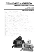
Summary of Contents for Explorer GPS GX1700

Page 1: ...oint with Compass page Navigation LAT LON SOG and COG information shown on display Submersible JIS 8 1 5M 4 92Ft for 30 minutes Noise canceling microphone with channel selection 16 9 and H L keys NOAA weather channel selection with alert Programmable Scan Priority Scan and Dual Watch Preset key stores up to 10 favorite channels with scan function Oversized dot matrix display with customizable chan...

Page 2: ...ATCH TO CHANNEL16 31 8 9 SCANNING 32 8 9 1 Scan Type Selection 32 8 9 2 Scan and P Scan Memory Programming 32 8 9 3 Memory Scanning M SCAN 33 8 9 4 Priority Scanning P SCAN 33 TABLE OF CONTENTS 8 10 PRESET CHANNELS 0 9 INSTANT ACCESS 34 8 10 1 Preset Channel Programming 34 8 10 2 Operation 34 8 10 3 Deleting a Preset Channel 34 8 11 INTERCOM OPERATION 35 8 11 1 Communication 35 8 11 2 Calling 35 9...

Page 3: ... 77 11 CHANNEL FUNCTION SETUP 78 11 1 CHANNEL GROUP USA CANADA or INTERNATIONAL BAND SELECTION 78 11 2 SCAN MEMORY CHANNEL 78 11 3 SCAN TYPE 79 11 4 SCAN RESUME 79 11 5 PRIORITY CHANNEL 80 11 6 WEATHER ALERT 80 11 7 CHANNEL NAME 81 12 DSC SETUP 82 12 1 INDIVIDUAL DIRECTORY 82 12 2 INDIVIDUAL REPLY 82 12 3 INDIVIDUAL ACKNOWLEDGMENT 82 12 4 INDIVIDUAL RINGER 82 12 5 GROUP DIRECTORY 82 12 6 POSITION ...

Page 4: ...io volume Rotate the SQL knob clockwise to the point where the noise not heard from the speaker Press the or microphones button to select the operating channel Press the or microphones button to toggle the transmit power between High 25W and Low 1W Press the or microphones button to recall channel 16 Press and hold the or microphones button to recall channel 9 Press again to revert to the last sel...

Page 5: ...e RF output power of 1 watt or 25 watts Other features of the GX1700 VHF s include Slim design only 3 5 deep Noise canceling microphone with controls optional RAM3 second station remote control microphone with display intercom between radio and optional RAM3 scanning priority scanning Dual Watch DSC Position Polling up to 4 vessels high and low voltage warning and GPS repeatability 2 PACKING LIST ...

Page 6: ... site from time to time may be beneficial to you as new products are released they will appear on the STANDARD HORIZON Web site PRODUCT SUPPORT INQUIRIES If you have any questions or comments regarding the use of the GX1700 you can visit the Marine Division of Vertex Standard Web site to send an E Mail or contact the Product Support team at 800 767 2450 M F 8 00AM to 5 00PM PST ...

Page 7: ...smitter On a fixed mount 25W radio transmission expected distances can be greater than 15 miles for a portable 5W radio transmission the expected distance can be greater than 5 miles in line of sight 5 3 SELECTING AN ANTENNA Marine antennas are made to radiate signals equally in all horizontal direc tions but not straight up The objective of a marine antenna is to enhance the signal toward the hor...

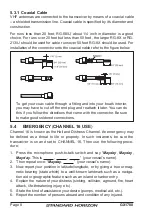
Page 8: ...connector Be sure to make good soldered connections 5 4 EMERGENCY CHANNEL 16 USE Channel 16 is known as the Hail and Distress Channel An emergency may be defined as a threat to life or property In such instances be sure the transceiver is on and set to CHANNEL 16 Then use the following proce dure 1 Press the microphone push to talk switch and say Mayday Mayday Mayday This is your vessel s name 2 T...

Page 9: ...ervals In areas of heavy radio traffic congestion on channel 16 resulting from its use as a hailing channel can be reduced significantly in U S 0waters by using channel 9 as the initial contact hailing channel for non emergency communications Also hailing on channel 9 the calling time should not exceed 30 seconds but may be repeated 3 times at 2 minute intervals Prior to making contact with anothe...

Page 10: ...l must concern navigation only such as meet ing and passing in restricted waters Channel 67 is used for navigational traffic between vessels By regulation power is normally limited to 1 Watt on these channels Your ra dio is programmed to automatically reduce power to this limit on these chan nels However in certain situations it may be necessary to temporarily use a higher power See page 25 key fo...

Page 11: ...7 Services International Southold Ch 28 Fort Myers Ch 27 Western LI Sound Ch 27 Horseshoe Beach Ch 26 Manasquan N J Ch 24 Islamorada Ch 26 Northern New Jersey Ch 27 Jacksonville Ch 27 Mid Atlantic Key Biscayne Ch 26 Atlantic City NJ Ch 26 Key Largo Ch 27 Central New Jersey NJ Ch 27 Marco Island Ch 27 Sea Isle Cape May NJ Ch 26 Naples Ch 26 Delaware River DE Ch 26 Palm Beach Ch 26 Northern Chesapea...

Page 12: ...llows connection to a power source and an antenna has nearby space for installation of a microphone hanger choose a mounting location that is at least 3 feet 1 m away from the radio s antenna choose a mounting location that the signal from the GPS satellite can receive sufficiently Note To insure the radio does not affect the compass or radios performance is not affected by the antenna location te...

Page 13: ...enna Q7000619A the GX1700 internal GPS Unit Power must be turned OFF refer to section 14 1 UNIT POWER and the GPS Selection changed to External GPS refer to section 14 9 GPS SELECTION 1 Use the supplied template to mark the location where the rectangular hole is to be cut Confirm the space behind the dash or panel is deep enough to accommodate the transceiver at least 3 54 inches 90 mm deep There ...

Page 14: ... the black power wire to a negative ground 3 If an optional remote extension speaker is to be used refer to section 6 5 ACCESSORY CABLE for connections 4 It is advisable to have a Certified Marine Technician check the power out put and the standing wave ratio of the antenna after installation Fuse Replacement 125V 6A To take out the Fuse from the Fuse Holder hold both ends of the Fuse Holder and p...

Page 15: ... GPS Input 12 V Battery 2 A Fuse Note The GPS antenna is supplied with 30ft of cable and a connector To connect the GPS antenna to the radio cut off the 5 pin antenna connector strip the white insulation to expose the Red Black and Brown wires and connect as shown in the diagram All other wires are not used and may be cut off The 2 amp fuse is not included Some GPS Chart plotters have a single wir...

Page 16: ...d When the GPS reception is limited such as the flush mounting of the GX1700 the NMEA input Blue and NMEA input Green wires may be connected to the NMEA output connections of a external GPS antenna or GPS Chart Plotter To change the GX1700 from using the internal GPS antenna to the external GPS antenna refer to section 14 9 GPS SELEC TION for selection and 14 1 UNIT POWER for turn off NMEA INPUT G...

Page 17: ...nal GPS antenna or a Chart Plotter is connected it must be setup to output GSA and GSV NMEA 0183 sentences 1 Press and hold down the key until Setup Menu appears then select GENERAL SETUP with the key 2 Press the soft key then select DIS PLAY with the key 3 Press the soft key then select GPS STATUS with the key 4 Press the soft key to display the GPS status currently being received 5 Press any key...

Page 18: ... select time offset of your location See illustration below to find your offset time If 00 00 is assigned the time is the same as UTC Universal Time Coordinated or GPS Satellite Time 4 Press the soft key to store the time offset 5 Press the soft key several times to return to radio operation Time Offset Table Setup Menu CH Function Setup DSC Setup GPS Setup MMSI Setup Waypoint Setup GENERAL SETUP ...

Page 19: ...ELECT GPS Setup TIME AREA Unit Power Coodinate System Pinning Time Offset Time Display QUIT ENT Time Area UTC Local 6 9 CHANGING THE TIME DISPLAY This menu selection allows the radio to setup to show time in 12 hour or 24 hour format 1 Press and hold down the key until Setup Menu appears then select GPS SETUP with the key 2 Press the soft key then press the key to select TIME DISPLAY 3 Press the s...

Page 20: ... Setup Setup Menu CH Function Setup DSC Setup Waypoint Setup MMSI Setup GPS SETUP QUIT SELECT QUIT SELECT GPS Setup MAGNETIC Coodinate System Pinning Time Offset Time Area Time Display QUIT ENT Magnetic TRUE Magnetic 6 11 OPTIONAL RAM3 CMP30 INSTALLATION The GX1700 is capable of using a RAM3 CMP30 Remote Station Micro phone to remotely control the Radio and DSC functions In addition the GX1700 can...

Page 21: ... Cap on to the Nut The installation is now complete Wall Gasket Mounting Bracket Routing Cable Cap Nut External Speaker Connections Ferrite Core NOTE The routing cable can be cut and spliced however care needs to be taken when reconnecting the wires to ensure water integrity Before cutting the cable make sure it is not plugged into the radio After cutting you will notice there are the following wi...

Page 22: ...s on routing cable to a fixed level regardless of the volume level setting of the RAM3 This is useful when using the optional MLS 310 amplified speaker with on off volume control 1 On the RAM3 mic press and hold the key until Setup Menu appears then select GENERAL SETUP with the key 2 Press the soft key 3 Press the key to until AF SELECT is shown and press the soft key 4 Press the or key to select...

Page 23: ... _ _ _ _ _ _ _ _ _ _ _ _ _ _ _ _ _ _ _ _ _ _ _ _ _ _ _ _ _ _ _ _ _ _ _ _ _ _ _ _ _ _ _ _ _ _ _ _ _ _ _ _ _ _ _ _ _ _ _ _ _ _ _ _ _ _ _ _ _ _ _ _ _ _ _ _ _ _ _ _ _ _ _ _ _ _ _ _ _ _ _ _ _ _ _ _ _ _ _ _ _ _ _ _ _ _ _ _ _ _ _ _ _ _ _ _ _ _ _ _ _ _ _ _ _ _ _ _ _ _ _ _ _ _ _ _ _ _ _ _ _ _ _ _ _ _ _ _ _ _ _ _ _ _ _ _ _ _ _ _ _ _ _ _ _ _ _ _ _ _ _ _ _ _ _ _ _ _ _ _ _ _ _ _ _ _ _ _ _ _ _ _ _ _ _ _ _ _ _ _...

Page 24: ...s Secondary use While holding down the soft key and pressing key you can confirm memory channels that have been programmed for scan ning Key Press the key briefly to recall channel 16 from any channel Press and hold the key to recall channel 9 Pressing the key again reverts to the previous selected working channel Key Turns the transceiver on and off To turn the transceiver on press and hold this ...

Page 25: ...ress and hold the key to access the SETUP MENU Key Press the key to toggle between 25 W High and 1 W Low power Channel 16 and 67 navigation Bridge channels are set 1 W however when the key is pressed the power on these channels may be tem porarily changed to 25 W until the PTT on the microphone is pressed and released The key does not function on transmit inhibited and low power only channels SQL ...

Page 26: ...onnects the GX1700 to a Chart Plotter or external GPS Antenna Refer to section 6 5 ACCESSORY CABLE External Speaker Connection Cable White Shield Connects the GX1700 to an external speaker See section 3 OPTIONS for a list of optional STANDARD HORIZON Speakers GND Terminal Ground Terminal Connecting a Ground wire to this connection will help reduce engine noise when receiving and transmitting Use t...
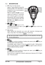
Page 27: ...er Microphone When spoken into transmits your voice with reduction of background noise using Clear Voice Noise Reduction Technology NOTE Be sure your mouth is about 1 2 inch 1 3 cm from the mic hole for best performance Key The key on the microphone functions the same as the key on the front panel of the transceiver Immediately recalls channel 16 from any channel location Holding down this key rec...

Page 28: ...or the radio is unsquelched 8 2 TRANSMISSION 1 Perform steps 1 through 6 of RECEPTION 2 Before transmitting monitor the channel to ensure it is clear THIS IS AN FCC REQUIREMENT 3 Press the PTT push to talk switch The TX indicator on the LCD is displayed 4 Speak slowly and clearly into the microphone 5 When the transmission is finished release the PTT switch NOTE This is a noise canceling microphon...

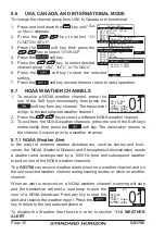
Page 29: ...key to select desired screen NORMAL COMPASS WAYPOINT or GPS STA TUS 5 Press the soft key to store the selected setting 6 Press the soft key several times to return to radio operation NOTE When the GPS STATUS mode is selected in step 4 above the dis play will stay the GPS Status until a key is pressed P CH SOG 25 0 COG 123 12 56 LOC AM 25W USA MP N W T DISTRESS 33 37 120 118 09 580 25W 16 North Up ...

Page 30: ...sturbances such as storms and hurri canes the NOAA National Oceanic and Atmospheric Administration sends a weather alert accompanied by a 1050 Hz tone and subsequent weather report on one of the NOAA weather channels The GX1700 can receive weather alerts when on a weather channel and on the last selected weather channel during scaning modes or while on another channel When an alert is received on ...

Page 31: ...iefly switches between the normal channel and Channel 16 to look for a transmission If the radio re ceives communications on channel 16 the radio stops and listens to Channel 16 until communication ends and then starts Dual watch scan again 1 Adjust the SQL knob until the background noise disappears 2 Select the channel you wish to dual watch to the priority channel 16 3 Press the one of the Soft ...

Page 32: ... Press the key to select PRIORITY SCAN or MEMORY SCAN 6 Press the soft key to store the selected setting 7 Press the soft key several times to return to radio operation Setup Menu CH Function Setup DSC Setup GPS Setup MMSI Setup Waypoint Setup GENERAL SETUP QUIT SELECT Setup Menu DSC Setup GPS Setup MMSI Setup Waypoint Setup CH FUNCTION SETUP QUIT SELECT General Setup CH Function Setup Scan Memory...

Page 33: ... is received 3 The channel number will blink during reception 4 To stop scanning press the key 8 9 4 Priority Scanning P SCAN By default Channel 16 is set as the priority channel You may change the priority channel to the desired channel from Channel 16 by the Radio Setup Mode refer to section 11 5 PRIORITY CHANNEL 1 Adjust the SQL knob until background noise disappears 2 Press the one of the Soft...

Page 34: ...ting the Preset Channel 3 Press the key key again to return to the last selected channel The P SET icon will disappear from the display 8 10 3 Deleting a Preset Channel 1 Press the key 2 Press the key to select the Preset Channel to be deleted 3 Press and hold the key until the channel number is blinking 4 Press the soft key momentarily to delete the channel from the Preset Channel 5 Repeat steps ...

Page 35: ...display Note A warning beep will be heard if the PTT button on the GX1700 and RAM3 CMP30 microphone are pushed simultaneously 4 Speak slowly and clearly into the microphone hold the microphone about 1 2 inch away from your mouth 5 When finished release the PTT switch 6 Press the soft key to exit intercom mode and revert to radio mode 8 11 2 Calling Press the soft key when in intercom mode on eithe...

Page 36: ... GMDSS Digital Selective Calling allows mariners to instantly send a distress call with GPS position when connected to the transceiver to the US Coast Guard and other vessels within range of the transmission DSC will also allow mariners to initiate or receive Distress Urgency Safety Routine Position Request Posi tion Report Automatic Position Polling and Group calls to or from another vessel equip...

Page 37: ... then press the soft key to step to the next number 5 Repeat step 4 to set your MMSI number nine digits 6 If a mistake was made entering in the MMSI number press the soft key until the wrong number is selected then press the key to correct the entry and press the soft key 7 When finished programming the MMSI number press and hold the soft key The radio will ask you to input the MMSI number again U...

Page 38: ...l an acknowledgment signal is received 4 If no acknowledgment is received the distress call is repeated in 4 minute intervals until a DSC ac knowledgment is received 5 When a DSC Distress acknowledgment is re ceived a distress alarm sounds and channel 16 is automatically selected The display shows the MMSI of the ship responding to your distress RECEIVED ACK acknowledgment signal is re ceived RECE...

Page 39: ...ll is repeated in 4 minute intervals until an acknowledgment is received 6 When a DSC Distress acknowledgment is re ceived a distress alarm sounds and channel 16 is automatically selected The display shows the MMSI of the ship responding to your distress RECEIVED ACK acknowledgment signal is re ceived RECEIVED RLY relay signal is received from an other vessel or coast station 7 Press the PTT butto...

Page 40: ...ess call is repeated in 4 minute intervals until an acknowl edgment is received 8 When a DSC Distress acknowledgment is re ceived a distress alarm sounds and channel 16 is automatically selected The display shows the MMSI of the ship responding to your distress RECEIVED ACK acknowledgment signal is re ceived RECEIVED RLY relay signal is received from an other vessel or coast station 9 Press the PT...

Page 41: ...el in distress To show additional information of the vessel in distress press the key refer to the second display On the display you will notice 3 soft key selections These selections are described below a Press to immediately select Channel 16 Note If a key is not pressed for 30 seconds or longer the radio will auto matically select Channel 16 b Temporarily suspend switching to channel 16 c Exit ...

Page 42: ... of the vessel in distress by a dot 7 To stop navigating to a waypoint press the one of the Soft keys then press the soft key The radio is switched to Normal Mode NOTE You must continue monitoring channel 16 as a coast station may re quire assistance in the rescue attempt Received DISTRESS DIST ID XXXXXXXXX WPT Name Position N W 33 39 220 118 10 560 QUIT ENT 25W 16 Range 50NM W E N S BRG 300 DST 4...

Page 43: ...Press the key to select the oper ating channel you want to communicate on then press the soft key If the chan nel you want to use is not listed press the soft key then press the key to select the operating channel you want to commu nicate on default is channel 16 then press the soft key 6 Press the soft key to transmit the selected type of all ships DSC call 7 After the All Ships Call is transmitt...

Page 44: ...ill notice 3 soft key selections These selections are described below a Accept to auto switching to Channel 16 Note If a key is not pressed for 30 seconds or lon ger the radio will automatically select Channel 16 b Temporarily suspend switching to channel 16 c Exit to the working channel 4 Press the soft key to return to the channel display Received All Ships Name Horizon ID 123456789 Since 01 03 ...

Page 45: ... the soft key 6 Press the key to scroll through the first letter of the name of the vessel or person you want to reference in the directory 7 Press the soft key to store the first letter in the name and step to the next letter to the right 8 Repeat step 6 and 7 until the name is complete The name can consist of up to eleven characters if you do not use all eleven characters press the soft key to m...

Page 46: ...ns When Manual is selected the MMSI of the calling vessel is shown allowing you to see who is calling This function is similar to caller id on a cellular phone 1 Press and hold down the key until Setup Menu appears 2 Press the key to select DSC SETUP menu 3 Press the soft key then select INDIVIDUAL REPLY with the key 4 Press the soft key 5 Press the key to select AUTOMATIC or MANUAL 6 Press the so...

Page 47: ...utes This selection allows the Individual Call ringer time to be changed 1 Press and hold down the key until Set up Menu appears 2 Press the key to select DSC SETUP menu 3 Press the soft key then select INDIVIDUAL RING with the key 4 Press the soft key 5 Press the key to select ringing time of a Individual Call 6 Press the soft key to store the se lected setting then press the soft key sev eral ti...

Page 48: ... allows the user to contact another vessel with a DSC radio This feature is similar to calling a vessel on CH16 and requesting to go to another channel 9 5 5 1 Individual Call using the Individual Directory 1 Press the key The DSC Menu will appear 2 Press the key to select INDIVIDUAL To cancel press the soft key 3 Press the soft key 4 Press the key to select the Individual you want to contact NOTE...

Page 49: ...ill show the name of the last person you called as shown in the display at the right If this is the case press the soft key and the following steps 4 Confirm MANUAL is selected then press the soft key 5 Press the key to select the first number of the MMSI which you want to contact then press the soft key to step to the next number 6 Repeat step 5 to set the MMSI number nine dig its 7 If a mistake ...

Page 50: ...efault setting to the calling ship and switch to the requested channel for voice communications Refer to section 9 5 2 Individual Reply Setup to change the reply to manual if you want to see who is calling before replying to the call 1 When an individual call is received an individual call ringing alarm sounds The radio automatically switches to the requested channel The display shows the MMSI of ...

Page 51: ...ted station 6 Press the soft key to resend the call if de sired 9 6 2 Reviewing DSC Distress Logged Calls The GX1700 radios allows DSC Distress Logged Calls to be reviewed 1 Press the key The DSC menu will ap pear 2 Press the key to select DSC LOG menu 3 Press the soft key then press the key to select DISTRESS LOG 4 Press the soft key then press the key to select the station name or MMSI number yo...

Page 52: ...Press the soft key then press the key to select the category TRANSMITTED LOG DISTRESS LOG or OTHER CALL LOG to be deleted 5 Press the soft key 1 If you want to delete all stations at a time select ALL LOG DELETE with the key then Group All Ships POS Request POS Report Auto POS Polling DSC Menu INDIVIDUAL QUIT SELECT Group All Ships POS Request POS Report Auto POS Polling DSC Menu DSC LOG QUIT SELE...

Page 53: ...w Are your sure Press the soft key 6 Press the soft key several times to return to radio operation View Log List All Log Delete Distress Log View Log List ALL LOG DELETE QUIT SELECT QUIT Distress Log Delete All directory Delete Log Complete QUIT Distress Log Delete All directory Delete Log Are your sure OK QUIT DELETE Distress Log 06 36 Pamle 18 42 SUN LIGHT 08 15 234567891 QUIT Distress Log Delet...

Page 54: ...MMSI numbers are not assigned by the FCC or other organiza tions licensed to assign ship MMSI numbers The first digit of a Group MMSI is always set to 0 by International rules All Standard Horizon radios are preset so when programming a Group MMSI the first digit is set to 0 The USCG recommends programming the MID of a ships MMSI into the Second Third and Fourth digits of the Group MMSI as it deno...

Page 55: ...e MMSI number are entered 11 If a mistake was made entering in the MMSI num ber repeat pressing the soft key until the wrong number is selected then press the key to correct the entry 12 To store the data entered press and hold the soft key 13 To enter another group address repeat steps 5 through 12 14 Press the soft key several times to return to radio operation 9 7 2 Transmitting a Group Call 9 ...

Page 56: ... soft key 5 Press the key to select the first number of the MMSI nine digits first digit permanently set to 0 which you want to contact then press the soft key to step to the next number 6 Repeat step 5 to set the MMSI number 7 If a mistake was made entering in the MMSI num ber repeat pressing the soft key until the wrong number is selected then press the key to correct the entry 8 When finished e...

Page 57: ...ou will notice 3 soft key selections These selections are described below a Press to immediately select Channel 16 Note If a key is not pressed for 30 seconds or longer the radio will auto matically select Channel 16 b Temporarily suspend switching to channel 16 c Exit to the working channel 5 If you want to respond monitor the channel to make sure it is clear then press the microphone s PTT switc...

Page 58: ...ection is important if you are concerned about someone polling the position of your vessel that you may not want to In the manual mode you will see the MMSI or persons name shown on the display allowing you to choose to send your position to the requesting vessel 1 Press and hold down the key until Setup Menu appears 2 Press the key to select DSC SETUP menu 3 Press the soft key then select POSITIO...

Page 59: ...ess the soft key to transmit the Position Request DSC call 6 When the GX1700 receives the position from the polled vessel it is shown on the radio dis play and also transferred to a GPS Chart plotter with NMEA DSC and DSE sentences 7 Press the soft key to return to radio opera tion Setup Menu CH Function Setup DSC Setup GPS Setup MMSI Setup Waypoint Setup GENERAL SETUP QUIT SELECT Setup Menu CH Fu...

Page 60: ...8 When finished entering the MMSI number press and hold the soft key 9 Press the key to select the nature of call ROUTINE or SAFETY then press the soft key 10 Press the soft key to transmit the position request DSC call 11 When the GX1700 receives the position from the polled vessel it is shown on the radio display and also transferred to the GPS Chart plotter with NMEA DSC and DSE sentences 12 Pr...

Page 61: ...ng your vessels position 2 To exit from position request display press the soft key Manually reply 1 When a position request call is received from an other vessel the display will be as shown in the illustration at the right 2 A ringing alarm sounds 2 minutes To send your vessels position to the requesting vessel press the soft key Or to exit from position re quest display press the soft key Recei...

Page 62: ...oft key then select Off with the key 6 Press the soft key to store the se lected setting 7 Press the soft key several times to return to radio operation To re enable the ringer tone repeat the above procedure pressing the key to select On in step 5 above 9 9 2 Transmitting a DSC Position Report Call 9 9 2 1 DSC Position Report Call using the Individual Directory 1 Press the key The DSC Menu will a...

Page 63: ...t step 5 to set the MMSI number 7 If a mistake was made entering in the MMSI num ber repeat pressing the soft key until the wrong number is selected then press the key to correct the entry 8 When finished entering the MMSI number press and hold the Press the soft key 9 Press the key to select the nature of call ROUTINE or SAFETY then press the soft key POS Report Call Vertex Bob Standard Sun Light...

Page 64: ... soft key 2 To start navigating using the compass display press and hold the soft key until the Compass Page is shown The display indicates the distance and direction of the received vessel and the compass indicates the received vessel by a dot icon 9 9 5 Stop Navigating to Position Report To stop navigating to a waypoint press the one of the Soft keys then press the soft key The radio is switched...

Page 65: ... hold down the key until Set up Menu appears 2 Select GENERAL SETUP with the key 3 Press the soft key 4 Select DISPLAY with the key and press the soft key 5 Select NORMAL with the key and press the soft key Received POS REPORT Name Horizon ID 123456789 Since 01 03 Category Routine QUIT TO WPT SAVE POS INFO ID 123456789 QUIT ENT BACK Waypoint Input WPT Name Horizon Position N W 33 33 120 118 06 230...

Page 66: ...ude of your vessel and your local UTC time in the 24 hour notation by the key Press the key to select the number and press the soft key to move the cursor to the next character You may backspace the cursor by pressing the soft key if you make a mistake 5 To store the data entered press and hold the soft key 6 Press the soft key several times to return to radio operation Setup Menu CH Function Setu...

Page 67: ... Press the key to select AUTO POS POLLING then press the soft key 3 Press the key to select the SE LECT ADDRESS then press the soft key 4 The radio will show 4 calling stations to be selected select CALL 1 and press the soft key 5 The radio will show the stations pro grammed in the Individual directory Press the key to select the desired sta tion and press the soft key Setup Menu CH Function Setup...

Page 68: ... 6 Press the soft key numerous times to exit to the radio mode NOTE When the radio receives position reports from a called vessel the display will show the image to the right also NMEA 0183 DSC and DSE sentences are outputted to a connected GPS Chart Plotter or PC Vertex Fisher USCG Auto POS Polling HORIZON QUIT SELECT Group All Ships POS Request POS Report Auto POS Polling DSC Menu INDIVIDUAL QUI...

Page 69: ... Directory Refer to section 9 5 1 Individual Position Call Directory Setup 9 12 2 DSC Test Call by using Individual Directory 1 Press the key The DSC Menu will appear 2 Press the key to select DSC TEST then press the soft key 3 Press the key to select the Ship name and press the soft key 4 Press the soft key to transmit the DSC test call to the other vessel Group All Ships POS Request POS Report A...

Page 70: ...Test Call reply from vessel that was called the radio will ring and show TEST ACK display which confirms the radio you called received the test call Group All Ships POS Request POS Report Auto POS Polling DSC Menu INDIVIDUAL QUIT SELECT All Ships POS Request POS Report Auto POS Polling DSC Log DSC Menu DSC TEST QUIT SELECT Test Call Test Call MANUAL QUIT SELECT Vertex Horizon Bob Standard Sun Ligh...

Page 71: ...he soft key to store the selected setting 6 Press the soft key several times to return to radio operation NORMAL Display COMPASS Display WAYPOINT Display P CH SOG 25 0 COG 123 12 56 LOC AM 25W USA MP N W T DISTRESS 33 37 120 118 09 580 25W 16 North Up W E N S COG 123 12 56 LOC AM N W T 33 37 120 118 09 580 SOG 25 0MP 25W 16 Range 50NM W E N S BRG 300 DST 45 0 12 56 LOC AM NM N W T 33 37 120 118 09...

Page 72: ... and hold down the key until Setup Menu appears then select GENERAL SETUP with the key 2 Press the soft key then press the key to select CONTRAST 3 Press the soft key 4 Press the key to select the desired level The contrast level can be set from 0 to 31 5 Press the soft key to store the selected level 6 Press the soft key several times to return to radio operation Setup Menu CH Function Setup DSC ...

Page 73: ...PEED DIS TANCE or ALTITUDE which you wish to change 5 Press the soft key then press the key to select desired unit Available selec tions are KTS knot MPH Mile Hour or KMH Kilo Meter Hour for speed NM Nautical Mile SM Statute Mile or KM Kilo Meter for distance and FT feet or M Meter for altitude 6 Press the soft key to store the selected setting 7 Press the soft key several times to return to radio...

Page 74: ...e soft key 4 Press the key to select the desired level The beep level can be set from LEVEL 1 to LEVEL 6 HIGH or OFF 5 Press the soft key to store the selected level 6 Press the soft several times to return to radio operation Setup Menu CH Function Setup DSC Setup GPS Setup MMSI Setup Waypoint Setup GENERAL SETUP QUIT SELECT General Menu Dimmer Display Contrast Station Name Unit of Measure KEY BEE...

Page 75: ...ete The name can consist of up to 8 characters if you do not use all 8 characters press the soft key to move to the next space This method can also be used to enter a blank space in the name If a mistake was made entering in the name repeat pressing the key until the wrong character is selected then press the key to correct the entry 9 Press and hold the soft key to enter the name 10 If you want t...

Page 76: ...ey to select the new function to be assigned and press the soft key Available functions are listed below Setup Menu CH Function Setup DSC Setup GPS Setup MMSI Setup Waypoint Setup GENERAL SETUP QUIT SELECT General Menu Dimmer Contrast Station Name Key Beep Unit of Measure SOFT KEY ASSIGNMENT QUIT SELECT Soft Keys Assignment Time Out Timer NUMBER OF SOFT KEYS QUIT SELECT Number of Soft Keys 4 5 8 6...

Page 77: ...y then press the key to select TIME OUT TIMER selects how long the soft key icon will be shown on the display after a soft key is pressed default is 4 seconds Then press the soft key 4 Press the key to select the time 5 Press the soft key to store the selected setting 6 Press the soft key several times to return to radio operation Setup Menu CH Function Setup DSC Setup GPS Setup MMSI Setup Waypoin...

Page 78: ...ned the press the key MEM icon appears on the display which indicates the channel has been selected to the scan channel 6 Repeat step 5 for all the desired channels to be scanned 7 To DELETE a channel from the list select the channel then press the key MEM icon disappears from the display 8 When you have completed your selection press the soft key sev eral times to return to radio operation Setup ...

Page 79: ... key 5 Press the key to select the desired re sume time default is 2 seconds The resume time can be set to 1SEC through 5SEC or OFF In the OFF selection the scanner will resume after the other station stops transmitting carrier drops 6 Press the soft key to store the selected setting 7 Press the soft key several times to return to radio operation Setup Menu CH Function Setup DSC Setup GPS Setup MM...

Page 80: ...key 4 Press the soft key 5 Press the key to select the desired WX alert mode The WX alert mode can be set to ON or OFF 6 Press the soft key to store the selected setting 7 Press the soft key several times to return to radio operation Setup Menu CH Function Setup DSC Setup GPS Setup MMSI Setup Waypoint Setup GENERAL SETUP QUIT SELECT Setup Menu DSC Setup GPS Setup MMSI Setup Waypoint Setup CH FUNCT...

Page 81: ...his method can also be used to enter a blank space in the name If a mistake was made entering in the name repeat pressing the key until the wrong character is selected then press the key to correct the entry 9 Press and hold the soft key to save the name 10 If you want to enter the name of another channel repeat steps 5 through 9 11 Press the soft key several times to return to radio operation Set...

Page 82: ...sel is shown allowing you to see who is calling This function is similar to caller id on a cellular phone Refer to section 9 5 2 Individual Reply Setup for setting 12 3 INDIVIDUAL ACKNOWLEDGMENT The radio can be setup to transmit a reply automatically default or set so the radio will not reply to an individual call Refer to section 9 5 3 Individual Acknowledgment Setup for setting 12 4 INDIVIDUAL ...

Page 83: ...s feature allows the alarm beeps to be turned on default setting or off when a DSC call is received The DSC calls that can be customized are In dividual Group All Ships Position Request Position Report Geographical Call using the procedure below 1 Press and hold down the key until Setup Menu appears 2 Press the key to select DSC SETUP menu 3 Press the soft key then select DSC BEEP with the key 4 P...

Page 84: ...y then select AUTO CH SWITCH TIME with the key 4 Press the soft key then press the key to the desired time and press the soft key 5 Press the soft key several times to return to radio operation Setup Menu CH Function Setup DSC Setup GPS Setup MMSI Setup Waypoint Setup GENERAL SETUP QUIT SELECT Setup Menu CH Function Setup GPS Setup MMSI Setup Waypoint Setup QUIT SELECT General Setup DSC SETUP DSC ...

Page 85: ...o store the first letter and to move to the second letter in the name 7 Repeat step 5 and 6 until the name is shown Press the soft key to skip a letter if need ed 8 Press and hold the soft key two times to save the waypoint into memory 9 Press the soft key several times to return to radio operation NOTE One of the soft keys refer to section 10 7 SOFT KEYS may be as signed to Mark and when pressed ...

Page 86: ... is shown include N or S in the last digit 12 Press the soft key to select the first digit of the Longitude is blink ing 13 Press the key to select the first digit in the Longitude 14 Press the soft key to store the first number and to move to the second number in the position 15 Repeat step 13 and 14 until the Latitude is shown include E or W in the last digit 16 After all information is entered ...

Page 87: ...r or number 9 Repeat step 7 and 8 until the waypoint is updated 10 Press and hold the soft key to store the edited waypoint into memory 11 Press the soft key several times to return to radio operation Setup Menu CH Function Setup DSC Setup GPS Setup MMSI Setup Waypoint Setup GENERAL SETUP QUIT SELECT General Setup Setup Menu CH Function Setup DSC Setup GPS Setup MMSI Setup WAYPOINT SETUP QUIT SELE...

Page 88: ...me will be flashing press the key to the first letter of the name you want to input 3 Press the soft key then press the key to select the second letter in the name 4 Repeat step 3 until the name is shown 5 Press and hold the soft key to save the waypoint to memory and return to radio operation Setup Menu CH Function Setup DSC Setup GPS Setup MMSI Setup Waypoint Setup GENERAL SETUP QUIT SELECT Gene...

Page 89: ...INT To stop navigating to a waypoint press the one of the Soft keys then press the soft key The radio is switched to Normal Mode Press the soft key to open the Waypoint Di rectory to select and navigate to a new waypoint Setup Menu CH Function Setup DSC Setup GPS Setup MMSI Setup Waypoint Setup GENERAL SETUP QUIT SELECT General Menu Dimmer Contrast Key Beep Station Name Unit of Measure DISPLAY QUI...

Page 90: ...old down the key until Set up Menu appears 2 Press the key to select WAY POINT SETUP 3 Press the soft key then select DIRECTION with the key 4 Press the soft key 5 Press the key to select desired direction 6 Press the soft key to store the se lected setting 7 Press the soft key several times to return to radio operation Setup Menu CH Function Setup DSC Setup GPS Setup MMSI Setup Waypoint Setup GEN...

Page 91: ... _ _ _ _ _ _ _ _ _ _ _ _ _ _ _ _ _ _ _ _ _ _ _ _ _ _ _ _ _ _ _ _ _ _ _ _ _ _ _ _ _ _ _ _ _ _ _ _ _ _ _ _ _ _ _ _ _ _ _ _ _ _ _ _ _ _ _ _ _ _ _ _ _ _ _ _ _ _ _ _ _ _ _ _ _ _ _ _ _ _ _ _ _ _ _ _ _ _ _ _ _ _ _ _ _ _ _ _ _ _ _ _ _ _ _ _ _ _ _ _ _ _ _ _ _ _ _ _ _ _ _ _ _ _ _ _ _ _ _ _ _ _ _ _ _ _ _ _ _ _ _ _ _ _ _ _ _ _ _ _ _ _ _ _ _ _ _ _ _ _ _ _ _ _ _ _ _ _ _ _ _ _ _ _ _ _ _ _ _ _ _ _ _ _ _ _ _ _ _ _...

Page 92: ...ress and hold down the key until Setup Menu appears 2 Press the key to select GPS SETUP 3 Press the soft key then select COORDI NATE SYSTEM with the key 4 Press the soft key then press the key to select the desired Coor dinate System The Coordinate System can be select to ddd mm ss ddd mm mm or ddd mm mmm 5 Press the soft key to save the new setting 6 Press the soft key several times to return to ...

Page 93: ... area The Time Offset must be changed in order for the radio to display the current time in your area Refer to section 6 7 CHANGING THE GPS TIME for setting 14 5 TIME AREA This selection allows the radio to show UTC time or local time with the offset Refer to section 6 8 CHANGING THE TIME AREA for setting 14 6 TIME DISPLAY This selection allows the radio to setup to show time in 12 hour or 24 hour...

Page 94: ...s This is a useful feature when the GX1700 is located in an area where GPS reception is limited NOTE When using an external GPS antenna or Chart plotter to input position data turn off the GPS receiver refer to section 14 1 UNIT POWER 1 Press and hold down the key until Setup Menu appears 2 Press the key to select GPS SETUP 3 Press the soft key then select GPS SELEC TION with the key 4 Press the s...

Page 95: ... SETUP 3 Press the soft key then select NMEA OUT PUT with the key 4 Press the soft key then press the key to select the desired sentence Avail able sentences are GLL GGA GSA GSV and RMC 5 Press the soft key then press the key to select On or Off 6 Press the soft key to save the new setting 7 Press the soft key several times to return to radio operation QUIT SELECT GPS Setup SBAS Time Area Time Dis...

Page 96: ...he radio manual The RAM3 is supplied with 23 feet 7 m of routing cable and can be extended up to 70 feet 21 m using three 23 foot extension cables model CT 100 The Inter com feature can be used between the RAM3 and the GX1700 In addition speaker wires are supplied at the panel mount of the routing cable for exter nal speakers to be connected in noisy environments 15 1 REMOTE MIC CONTROLS KEY Toggl...

Page 97: ...e key briefly the key functions will appear at the bottom of the display Refer to section 15 2 ASSIGNING SOFT KEYS for details KEY PAD Key Press this key to access the DSC menu Press and hold this key to access the SETUP menu Key First press channel 16 is immediately selected Second press recalls the last selected channel Press and hold selects channel 9 UP DOWN Key These keys are used to select c...

Page 98: ...the key to select SOFT KEY 3 Press the soft key then press the key to select NUMBER OF SOFT KEYS 4 Press the soft key then press the or key to select the number of soft keys 3 through 10 5 Press the soft key then press the key to select KEY ASSIGNMENT to change the use of selected soft keys Then press the soft key 6 Press the or key to select the key KEY1 KEY2 KEY3 etc and press the soft key Then ...

Page 99: ... FUNCTION SCAN Starts and stops Scanning DW Starts and stops Dual Watch Scan IC Activates Intercom between radio and RAM3 mic optional RAM3 required CMP COMPASS Shows to the Compass display WPT Shows to the Waypoint Navigation display PRESET Saves or deletes the preset memory channel WX Immediately recalls the last select the weather channel MARK Marks the current position for a Waypoint PRESET 0 ...

Page 100: ...erious problems please contact your Dealer or our repair facility Address and phone numbers for this facility as well as war ranty information are contained in section 18 WARRANTY 16 1 REPLACEMENT PARTS Occasionally an owner needs a replacement mounting bracket or knob These can be ordered from our Parts Department by writing or calling Marine Division of Vertex Standard US Headquarters 6125 Phyll...

Page 101: ...re the red wire is connected to the positive battery post and the black wire is connected to the negative bat tery post If the fuse still blows contact your Dealer Popping or whin ing noise from the speaker while engine runs Engine noise Re route the DC power cables away from the engine Add noise suppressor on pow er cable Change to resistive spark plug wires and or add an alternator whine filter ...

Page 102: ...os indicate an A adjacent to the alpha channels on the display on others alpha is not indicated but the proper channel is selected based on the U I C setting 3 Bridge to Bridge channels for example Channel 13 are for use by bridge operators on inter coastal waterways and rivers It is also used by marine vessels in the vicinity of these bridges for navigation and for com municating with the bridge ...

Page 103: ...lopment Corporation or the U S Coast Guard The use of these fre quencies outside VTS and ship movement sector protected areas is per mitted provided they cause no interference to VTS and ship movement communications in their respective designated sectors 10 Use of 156 875 MHz is limited to communications with pilots regarding the movement and docking of ships Normal output power must not ex ceed 1...

Page 104: ...side Puget Sound area and its approaches and the Great Lakes 157 425 MHz is also available for communications between com mercial fishing vessels and associated aircraft while engaged in commer cial fishing activities 14 When the frequency 156 850 MHz is authorized it may be used addition ally for search and rescue training exercises conducted by state or local governments 15 The frequency 156 850...

Page 105: ...ship Navigation Safety Bridge to bridge 14 X X X S 156 700 Port operation VTS in selected areas 15 X S 156 750 Environmental Receive only 15 X X S 156 750 Commercial non commercial ship movement 1 W 16 X X X S 156 800 International Distress Safety and Calling 17 X X X S 156 850 State Controlled 1 W 18 X D 156 900 161 500 Port operation ship movement 18A X X S 156 900 Commercial 19 X D 156 950 161 ...

Page 106: ...s 67 X X X S 156 375 US Commercial Used for Bridge to bridge communi cations in lower Mississippi River Inter ship only Canada Commercial fishing S R 68 X X X S 156 425 Non commercial Recreational 69 X X X S 156 475 US Non commercial Recreational Canada Commercial fishing only International Inter ship Port operations and Ship movement 70 X X X S 156 525 Digital selective calling voice communicatio...

Page 107: ...ce Marine Operator 83A X X S 157 175 U S Government Only Canadian Coast Guard Only 84 X X X D 157 225 161 825 Public Correspondence Marine Operator 85 X X X D 157 275 161 875 Public Correspondence Marine Operator 86 X X X D 157 325 161 925 Public Correspondence Marine Operator 87 X X S 157 375 Port operation ship movement 87A X S 157 375 Public Correspondence Marine Operator 88 X X S 157 425 Port ...

Page 108: ...01 91 Associated Chargers 1 year if purchased before 01 01 91 3 years if purchased after 01 01 91 Associated Batteries 1 year Note Batteries will be deemed deflective only if storage capacity drops below 80 of rated capacity or if leakage de velops Associated Accessories 1 year Includes Microphones Handsets Exter nal Speakers Antennas Carrying Accessories Power Supplies and Signal ing Boards To re...

Page 109: ...y Product which has been sub jected to misuse neglect accident incorrect wiring by anyone other than STANDARD HORIZON improper installation or subjected to use in violation of instructions furnished by STANDARD HORIZON nor does this warranty extend to Products on which the serial number has been removed defaced or changed STANDARD HORIZON cannot be responsible in any way for an cillary equipment n...

Page 110: ...e states do not allow the exclusion or limitation of incidental or conse quential damages or limitation on how long an implied warranty lasts so the above limitations or exclusions may not apply This warranty gives spe cific legal rights and there may be other rights which may vary from state to state ONLY PRODUCTS SOLD ON OR AFTER JANUARY 1 1991 ARE COV ERED UNDER THE TERMS OF THIS LIMITED WARRAN...

Page 111: ...ion to the warranty STANDARD HORIZON includes a lifetime flat rate and customer loyalty programs to provide service after the warranty period has expired If you wish to obtain the flat rate price for out of warranty repair you must include the information on the Owner s Record with the unit when you return it to your Dealer or to STANDARD HORIZON Lifetime Flat Rate Service Program For the original...

Page 112: ...ing the radio on 19 2 MICROPROCESSOR RESET To clear all memories and other settings to factory defaults except the Chan nel Group MMSI number and DSC directory information 1 Turn the radio off 2 Press and hold in the and keys while turning the radio on While resetting the radio the display will show the display to the right for about 10 seconds then turn on Resetting EE PROM ...

Page 113: ..._ _ _ _ _ _ _ _ _ _ _ _ _ _ _ _ _ _ _ _ _ _ _ _ _ _ _ _ _ _ _ _ _ _ _ _ _ _ _ _ _ _ _ _ _ _ _ _ _ _ _ _ _ _ _ _ _ _ _ _ _ _ _ _ _ _ _ _ _ _ _ _ _ _ _ _ _ _ _ _ _ _ _ _ _ _ _ _ _ _ _ _ _ _ _ _ _ _ _ _ _ _ _ _ _ _ _ _ _ _ _ _ _ _ _ _ _ _ _ _ _ _ _ _ _ _ _ _ _ _ _ _ _ _ _ _ _ _ _ _ _ _ _ _ _ _ _ _ _ _ _ _ _ _ _ _ _ _ _ _ _ _ _ _ _ _ _ _ _ _ _ _ _ _ _ _ _ _ _ _ _ _ _ _ _ _ _ _ _ _ _ _ _ _ _ _ _ _ _ _ ...

Page 114: ...dual Call Directory 80 Group Call Directory 32 Waypoint Directory 100 LCD Display Type 2 75 x 1 33 70 x 34 mm Full Dot Matrix 132 x 64 pixels Dimensions WxHxD 5 9 x 3 4 x 3 5 150 x 85 x 90 mm Flush Mount Dimensions WxHxD 5 4 x 2 8 x 2 6 137 x 72 x 65 mm Weight 2 0 lbs 0 9 kg 20 2 TRANSMITTER Frequency Range 156 025 MHz to 157 425 MHz RF Output Power 25 W Hi 1 W Lo Conducted Spurious Emissions Less...

Page 115: ...r DSC Audio Output 4 5 W at 4 ohms external speaker output Audio Response within 1 3dB of a 6 dB Octave de emphasis characteristic at 300 to 3000 Hz Frequency Stability 0 0003 4 F to 140 F 20 C to 60 C Channel Spacing 25 kHz DSC Format ITU R M 493 13 20 4 GPS UNIT Receiver Channels 12 Channels Sensitivity Less than 130 dBm Time to First Fix 1 minute typical Cold Start 40 seconds typical Warm Start...

Page 116: ...GX1700 Page 116 20 6 DIMENSIONS 5 9 150 mm 3 4 85 mm 5 4 136 mm 1 40 1 mm 6 2 6 66 mm 1 4 36 mm 0 8 19 1 mm 1 1 27 7 mm 3 4 85 mm 2 8 71 mm ...

Page 117: ...Page 117 GX1700 6 9 174 4 mm 5 4 136 mm 5 9 150 mm 5 9 150 mm 3 4 85 mm 4 4 110 5 mm 0 8 19 1 mm 2 7 69 5 mm 1 6 40 1 mm 2 6 65 mm 1 4 36 mm 1 1 27 7 mm 3 4 85 mm 2 8 71 mm ...

Page 118: ...5 605 html To obtain a form from the FCC call 888 225 5322 21 2 RADIO CALL SIGN Currently the FCC does not require recreational boaters to have a Ship Ra dio Station License The USCG recommends the boats registration number and the state to be used when calling another vessel 21 3 CANADIAN SHIP STATION LICENSING You may need a license when traveling in Canada If you do need a license contact their...

Page 119: ... reasonable protection against harmful interference in a residential installation This equipment generates uses and can radiate radio frequency energy and if not installed and used in accordance with the instructions may cause harmful interference to radio communications However there is no guarantee that interference will not occur in a particular installation If this equipment does cause harmful...

Page 120: ...11 VERTEX STANDARD CO LTD All rights reserved No portion of this manual may be reproduced without the permission of VERTEX STANDARD CO LTD Printed in China 6125 Phyllis Drive Cypress California 90630 U S A www standardhorizon com ...

Reviews: