background image

- 5 -

EN

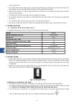
To connect the unit to an electrical equipotential bonding system:


unscrew the nut on the screw


insert the equipotential bonding wire


Screw the nut back on as far as it will go


Connect the other end of the equipotential bonding conductor to the equipotential bonding rail.

Fig. 4 Connecting the device to an electrical equipotential bonding system


1. 

Terminal box

2. 

Equipotential bonding screw

3. 

Nameplate

Fig. 5 Rear view oft he device.

The supply cable shou Id be a flexible, oil-resistant cable with a grounding conductor, with a polychloropre-

ne sheath - this can be prepared by the manufacturer and available from him or from specialist repair shops!

PE- protective conductor (yellow-green)
N - neutral wire (blue)
L1, L2, L3 - phase wires (other colors)

Fig. 7 Connecting the device to the electrical installation


The unit may only be connected to the mains by a person with electrical qualifications


The device should be connected to a three-phase socket supplied with electricity 400V SOHz equipped 

with a circuit breaker with residual current protection ln=30mA by means of a plug or directly to the 

power supply system.

5.  DEVICE OPERATION

Before switching on the device, make sure that it has been installed correctly and is in a condition 

for safe operation.

Preparation forstarting the device: 

Summary of Contents for 965001

Page 1: ...Sp z o o Plac Konesera 9 Budynek O 03 736 Warszawa tel 22 517 15 75 fax 22 517 15 77 www stalgast com email stalgast stalgast com Multi funcional electrical oven User manual translation of the origin...

Page 2: ...Fig 1 Fig 2...

Page 3: ...d and possibly repaired at a speciali zed repair facility before further use Never repair the unit yourself doing so may endanger your life Unauthorized alterations or repairs are prohibited Protect t...

Page 4: ...nsions of the oven chamber mm 610x440x285 Grate size mm 600x400 oraz 1 1 GN Power supply V Hz 400 50 Power cord mm2 5 x 2 5 4 INSTALLATION Before initial operation remove the protective film from the...

Page 5: ...pre ne sheath this can be prepared by the manufacturer and available from him or from specialist repair shops PE protective conductor yellow green N neutral wire blue L1 L2 L3 phase wires other colors...

Page 6: ...low item 4 the heater cannot operate without the fan The fan generates air movement using such heating method allows for even heat circulation around the food placed in the oven When the orange lamp i...

Page 7: ...th sheet metal screws removed from the rear housing and supplied with the connectors 6 CLEANING AND MAINTENANCE Disconnect the unit from the power source before performing any maintenance Daily mainte...

Page 8: ...cal website or the notice board of the municipal office Leave the equipment at a service point If the repair of the equipment is unprofitable or impossible for technical reasons the service is obliged...

Reviews: