background image

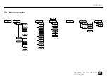
7.3  Menu overview

MENU

Pro

Pr.01

SLAv

AUTO

Set

InFo

-Yes

-NO

-rSt

Ver

Temp

d---

d.001

5.-CH

7.-CH

9.-CH

80.CH

d.512

CuSe

Cu-4

Pr.02

SP.01

SP.99

FS.00

FS.99

CoLr

r.000

r.255

g.000

g.255

b.000

b.255

A.000

A.255

u.000

u.255

FS.00

FS.99

Pr.25

1.

xxx

19.on

-OFF

SP.FL

FS.00

FS.99

Cu-1

Operating


Show Bar Pro 16x10W RGBAW IP65

29

LED Floodlight

Summary of Contents for Show Bar Pro

Page 1: ...Show Bar Pro 16x10W RGBAW IP65 LED Floodlight User Manual...

Page 2: ...Thomann GmbH Hans Thomann Stra e 1 96138 Burgebrach Germany Telephone 49 0 9546 9223 0 Internet www thomann de 29 07 2022 ID 379792 V4...

Page 3: ...15 5 Starting up 19 6 Connections and controls 21 7 Operating 23 7 1 Starting the device 23 7 2 Main menu 23 7 3 Menu overview 29 7 4 Functions in 5 channel DMX mode 30 7 5 Functions in 7 channel DMX...

Page 4: ...9 Plug and connection assignments 41 10 Troubleshooting 42 11 Cleaning 44 12 Protecting the environment 45 Table of contents 4 Show Bar Pro 16x10W RGBAW IP65 LED Floodlight...

Page 5: ...Show Bar Pro 16x10W RGBAW IP65 5 LED Floodlight...

Page 6: ...to all persons using this device If you sell the device to another user be sure that they also receive this manual Our products and user manuals are subject to a process of continuous development We t...

Page 7: ...n to find the topics of interest for you quickly Online guides Our online guides provide detailed information on technical basics and terms Personal consultation For personal consultation please conta...

Page 8: ...Meaning DANGER This combination of symbol and signal word indicates an immediate dangerous situation that will result in death or serious injury if it is not avoided WARNING This combination of symbol...

Page 9: ...signs Type of danger Warning high voltage Warning hot surface Warning dangerous optical radiation Warning suspended load Warning danger zone General information Show Bar Pro 16x10W RGBAW IP65 9 LED Fl...

Page 10: ...ies and having corresponding knowledge and experience Other persons may use this device only if they are supervised or instructed by a person who is responsible for their safety Extend the operating l...

Page 11: ...ical components are missing or damaged WARNING Eye damage caused by high light intensity Never look directly into the light source WARNING Risk of epileptic shock Strobe lighting can trigger seizures...

Page 12: ...c shock or fire NOTICE Fire hazard due to exceedance of the maximum current The device can power other devices of identical construction The current consumption of all other devices connected in serie...

Page 13: ...e optionally available IP65 DMX adapter cable automatic with 25 preprogrammed shows master slave manually via buttons and display at the unit n robust and weatherproof metal housing n various mounting...

Page 14: ...the equipment resistance to changing ambient conditions as well as against the effects of sun light and UV rays The seals and screw connections of the equipment must be checked regularly to ensure a...

Page 15: ...torage respectively WARNING Risk of injury caused by falling objects Make sure that the installation complies with the standards and rules that apply in your country Always secure the device with a se...

Page 16: ...or free operation make use of dedicated DMX cables and do not use ordi nary microphone cables Never connect the DMX input or output to audio devices such as mixers or ampli fiers NOTICE Possible damag...

Page 17: ...the coupling Hand tighten the union nut You can install the device on the wall the ceiling or on the floor Two mounting brackets and the necessary screws are included Always work from a stable platfor...

Page 18: ...o 437012 can be fixed at the front of the unit with four undetachable thumb screws Place the filter onto the front side and tighten the screws successively finger tight Attaching the filter Installati...

Page 19: ...of the device to the DMX output of a DMX controller or another DMX device Connect the output of the first DMX device to the input of the second one and so on to form a series connection Such a chain m...

Page 20: ...is especially useful to start a show without much programming Connect the DMX output of the master unit to the DMX input of the first slave unit Then connect the DMX output of the first slave unit to...

Page 21: ...ket Power Twist TR1 IP65 for power supply 3 DMX input 4 Locking screws for locking the mounting bracket in the desired orientation 5 Horizontally slidable mounting bracket which is adjustable in incli...

Page 22: ...les between menu items 11 SETUP selects an option of the respective operating mode 12 UP navigates upwards in a menu list Increases the displayed value by one 13 DOWN navigates downwards in a menu lis...

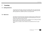
Page 23: ...E to activate the main menu and select an operating mode Use SETUP to select further options Use UP and DOWN to change the respectively displayed value When the display shows the desired value press S...

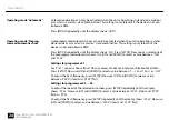
Page 24: ...etween Pr 01 and Pr 25 Settings for programme 01 For Pr 01 you can choose from 19 basic colours maximum intensity or blackout of all LEDs Press SETUP Now use UP and DOWN to select a value between 1 r...

Page 25: ...to be used by the device DMX address Use UP and DOWN to select a value between 1 and 512 display shows d 001 d 512 Make sure that this number matches the configuration of your DMX controller The foll...

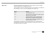
Page 26: ...ss MODE repeatedly until the display shows CoLr Press SETUP Use UP and DOWN to select one of the following options Display Meaning r 000 r 255 Red g 000 g 255 Green b 000 b 255 Blue u 000 u 255 White...

Page 27: ...e with a flat profile at the beginning and a steep profile at the end Square Cu 3 Inverted quadratic curve with a steep profile at the beginning and a flat profile at the end Inv Square Cu 4 Non linea...

Page 28: ...Fo Press SETUP Use UP DOWN to select the menu item Ver and confirm with SETUP to let the device show the firmware ver sion Press MODE repeatedly until the display shows InFo Press SETUP Use UP DOWN to...

Page 29: ...er Temp d d 001 5 CH 7 CH 9 CH 80 CH d 512 CuSe Cu 4 Pr 02 SP 01 SP 99 FS 00 FS 99 CoLr r 000 r 255 g 000 g 255 b 000 b 255 A 000 A 255 u 000 u 255 FS 00 FS 99 Pr 25 1 xxx 19 on OFF SP FL FS 00 FS 99...

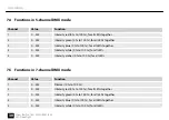
Page 30: ...tensity white 0 to 100 for all LEDs 5 0 255 Intensity amber 0 to 100 for all LEDs 7 5 Functions in 7 channel DMX mode Channel Value Function 1 0 255 Dimmer 0 to 100 2 0 255 Intensity red 0 to 100 for...

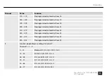
Page 31: ...l DMX mode Channel Value Function 1 0 255 Dimmer 0 to 100 2 0 255 Intensity red 0 to 100 3 0 255 Intensity green 0 to 100 4 0 255 Intensity blue 0 to 100 5 0 255 Intensity white 0 to 100 6 0 255 Inten...

Page 32: ...0 79 Preprogrammed automatic show 08 80 89 Preprogrammed automatic show 09 90 99 Preprogrammed automatic show 10 100 109 Preprogrammed automatic show 11 110 119 Preprogrammed automatic show 12 120 129...

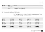
Page 33: ...ow 22 220 229 Preprogrammed automatic show 23 230 239 Preprogrammed automatic show 24 240 255 Preprogrammed automatic show 25 8 Function depending on setting of channel 7 Channel 7 1 9 0 12 Blackout R...

Page 34: ...0 B 0 W 200 A 0 156 168 R 0 G 255 B 0 W 500 A 0 169 181 R 0 G 0 B 255 W 200 A 0 182 194 R 255 G 0 B 0 W 0 A 255 195 207 R 0 G 255 B 0 W 0 A 255 208 220 R 0 G 0 B 255 W 0 A 255 221 233 R 0 G 0 B 0 W 2...

Page 35: ...hannel 3 Channel 4 Channel 5 Red LED 1 Green LED 1 Blue LED 1 White LED 1 Amber LED 1 Channel 6 Channel 7 Channel 8 Channel 9 Channel 10 Red LED 2 Green LED 2 Blue LED 2 White LED 2 Amber LED 2 Channe...

Page 36: ...Blue LED 8 White LED 8 Amber LED 8 Channel 41 Channel 42 Channel 43 Channel 44 Channel 45 Red LED 9 Green LED 9 Blue LED 9 White LED 9 Amber LED 9 Channel 46 Channel 47 Channel 48 Channel 49 Channel...

Page 37: ...D 14 Blue LED 14 White LED 14 Amber LED 14 Channel 71 Channel 72 Channel 73 Channel 74 Channel 75 Red LED 15 Green LED 15 Blue LED 15 White LED 15 Amber LED 15 Channel 76 Channel 77 Channel 78 Channel...

Page 38: ...nnels 5 7 9 or 80 Input connections Power supply Lockable input socket Power Twist TR1 IP65 DMX control XLR chassis plug 3 pin Output connections Power supply of further devices Lockable output socket...

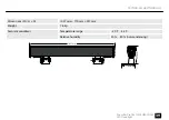
Page 39: ...0 mm 221 mm Weight 7 6 kg Ambient conditions Temperature range 20 C 45 C Relative humidity 20 80 non condensing MODE SETUP UP DOWN 1027 mm 221 mm 170 mm Technical specifications Show Bar Pro 16x10W RG...

Page 40: ...door use yes fanless yes Remote control Not possible Wireless DMX no Housing colour black Separately controllable LEDs yes Further information Technical specifications 40 Show Bar Pro 16x10W RGBAW IP6...

Page 41: ...esult of an incorrect connection may be a destroyed DMX controller a short circuit or just a not working light show The unit offers a 3 pin XLR socket for DMX output and a 3 pin XLR plug for DMX input...

Page 42: ...do not use ordi nary microphone cables Never connect the DMX input or output to audio devices such as mixers or ampli fiers In the following we list a few common problems that may occur during operati...

Page 43: ...ection 2 If the display does not flash and still no response check the address settings and the DMX polarity 3 Try using another DMX controller 4 Check to see if the DMX cables run near or alongside t...

Page 44: ...lean with a soft cloth using our lamp and lens cleaner item no 280122 n Always dry the parts carefully The fan grids of the device must be cleaned of any contamination such as dust etc on a reg ular b...

Page 45: ...kings on the packaging This product is subject to the European Waste Electrical and Electronic Equipment Directive WEEE in its currently valid version Do not dispose with your normal household waste D...

Page 46: ...Notes 46 Show Bar Pro 16x10W RGBAW IP65 LED Floodlight...

Page 47: ......

Page 48: ...Musikhaus Thomann Hans Thomann Stra e 1 96138 Burgebrach Germany www thomann de...

Reviews: