Page 100
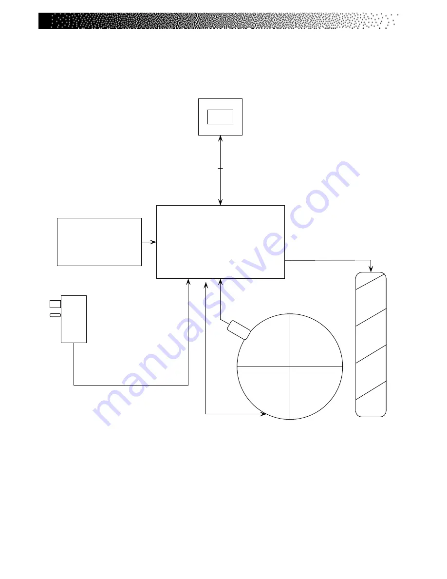
Figure 50: Wiring Diagram
P ow er B oard
P/N 1 3 5 7 2
B A T T E R Y
P / N 1 4 1 2 3
Req uires 6.0 VD C to s tart Un it
Ch arge for 24HRS b efore
rep lac em ent.
B a tte ry C h a rg e r
P/N 2 5 0 6 7
B C - 1 ( 3 - Pin )
I n d u c tiv e
S w itc h
P/N 2 1 4 4 5
A ltern a to r
P /N 2 0 2 0 5
L oad R es is tor
P/N 2 5 6 1 1
.5 O h m 2 4 0 W a t t
P o s itive
O u tput
( B + )
( W H I TE)
G ro und
T e rm ina l
( B L A C K )
F ie ld
T e rm ina l
( B R O W N)
3 4 0 0 U p pe r M a in C a ble
P/N 2 5 4 6 2
C o n s o le t o I n lin e C o n n e ct o r
3 4 0 0 L o w e r M a in C a ble
P/N 2 5 4 6 3
I n lin e C o n n e ct o r t o PC B A ( Po we r B o a rd)
C o ns o le C 4 0
P/N 2 7 7 9 6
M u s t co n f ig u re f o r C y cle
Us e ^ 8 0
A lt e rn a t o r
W irin g
H a rn e s s
P/N 1 3 5 8 4
3 8 0 0 M a in C a ble
P/N 2 5 4 7 3
C o n s o le t o PC B A
Summary of Contents for FreeClimber
Page 12: ...Page 13 BISON TRANSMISSION DETAIL...
Page 15: ...Page 16 Figure 1 Final Assembly Left 4600 PT...
Page 16: ...Page 17 Figure 2 Final Assembly Right 4600 PT...
Page 17: ...Page 18 Figure 3 Final Assembly Left 4600 CL...
Page 18: ...Page 19 Figure 4 Final Assembly Right 4600 CL...
Page 19: ...Page 20 Figure 5 Covers 4600 PT CL...
Page 20: ...Page 21 Figure 6 Pedal Arm Assembly First Reduction Shaft Assembly 4600 4400 PT CL 4200 PT...
Page 21: ...Page 22 Figure 7 Drive Shaft Assembly Eccentric Hub Assembly 4600 4400 PT CL 4200 PT...
Page 22: ...Page 23 Figure 8 Final Assembly Left 4400 4200 PT...
Page 23: ...Page 24 Figure 9 Final Assembly Right 4400 4200 PT...
Page 24: ...Page 25 Figure10 Final Assembly Left 4400 CL...
Page 25: ...Page 26 Figure 11 Final Assembly Right 4400 CL...
Page 26: ...Page 27 Figure 12 Covers 4400 PT CL 4200 PT...
Page 27: ...Page 28...
Page 35: ...Page 36...
Page 38: ...Page 39...
Page 40: ...Page 41 Figure 13 Parts Needing Periodic Lubrication...
Page 41: ...Page 42 Figure 14 Side Cover and Handrail Assemblies...
Page 42: ...Page 43 Figure 15 Poly V Belt Tension...
Page 43: ...Page 44 Figure 16 Drive Chain Assembly...
Page 44: ...Page 45 Figure 17 Step Assembly...
Page 45: ...Page 46 Figure 18 Step Chain and Sprocket Assemblies...
Page 46: ...Page 47 Figure 19 Transmission and Alternator Assemblies...
Page 47: ...Page 48 Figure 20 Wiring Diagram 1...
Page 48: ...Page 49 Figure 21 Wiring Diagram 2...
Page 49: ...Page 50 Figure 22 Wiring Diagram 3...
Page 56: ...Page 57 ELECTRICAL DETAIL...
Page 57: ...Page 58 SAFETY VALVE...
Page 62: ...Page 63 Figure 23 Right Side View 1650 LE...
Page 63: ...Page 64 Figure 24 Left Side View 1650 LE...
Page 64: ...Page 65 Figure 25 Pedal Arm Assembly...
Page 65: ...Page 66 Figure 26 Right Side View 2650 UE...
Page 66: ...Page 67 Figure 27 Top View 2650 UE...
Page 67: ...Page 68 Figure 28 Weight Stack Assembly...
Page 73: ...Page 74 Figure 29 3300 CE Right Side View...
Page 74: ...Page 75 Figure 30 3300 CE Left Side View...
Page 75: ...Page 76 Figure 31 3900 RC Right Side View...
Page 76: ...Page 77 Figure 32 3900 RC Left Side View...
Page 77: ...Page 78 Figure 33 3300 CE Seat Adjustment Pin...
Page 78: ...Page 79 Figure 34 3900 RC Seat Assembly...
Page 79: ...Page 80 Figure 35 Drive Chain Assembly...
Page 80: ...Page 81 Figure 36 Intermediate Shaft Assembly...
Page 81: ...Page 82 Figure 37 J Bolt Assembly...
Page 82: ...Page 83 Figure 38 Crank Assembly...
Page 83: ...Page 84 Figure 39 Alternator Assembly...
Page 89: ...Page 90 Figure 40 Final Assembly Right Side View 3400 CE...
Page 90: ...Page 91 Figure 41 Final Assembly Left Side View 3800 RC...
Page 91: ...Page 92 Figure 42 Seat Post Assembly 3400 CE...
Page 92: ...Page 93 Figure 43 Seat Assembly 3800 RC...
Page 93: ...Page 94 Figure 44 Seat Track Assembly 3800 RC...
Page 94: ...Page 95 Figure 45 Intermediate Poly V Assembly...
Page 96: ...Page 97 Figure 47 Alternator Flywheel Assembly...
Page 97: ...Page 98 Figure 48 Wire Connections...
Page 98: ...Page 99 Figure 49 Power Control Board Plug Ins...
Page 101: ...Page 102...
Page 102: ...Page 103...
Page 103: ...Page 104...
Page 104: ...Page 105...
Page 105: ...Page 106...


