ENENENENENENENENENENENENENENENENENENENENENENENENEN
Operating instructions
Additional languages r-stahl.com
EN
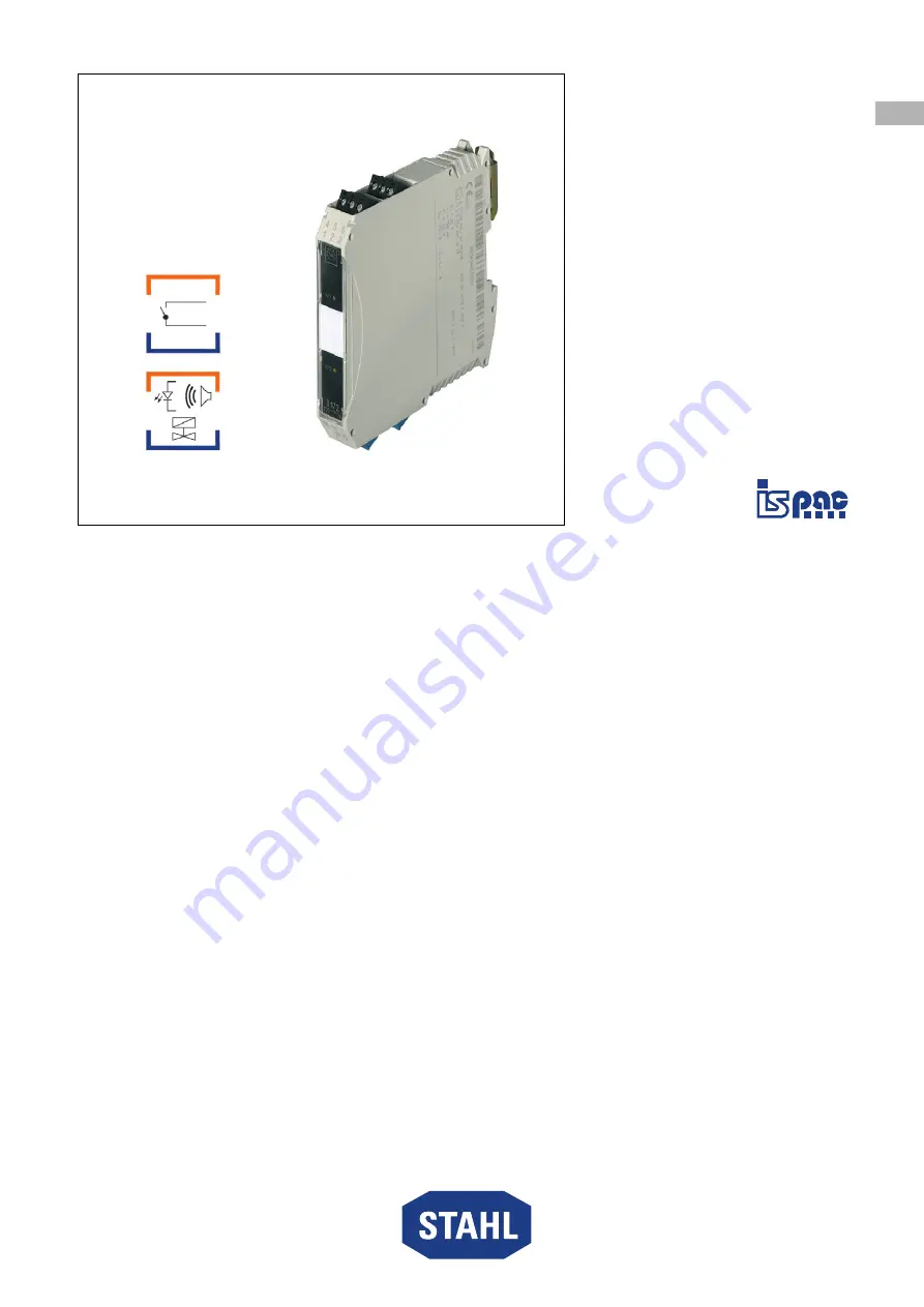
I.S. Relay Module
Series 9172
– Save f
or future
use! –
Page 1: ...DE DE DE DE DE DE DE DE DE DE DE DE DE DE DE DE DE DE DE DE DE DE DE DE DE Betriebsanleitung Additional languages r stahl com DE Ex i Relais Modul Reihe 9172 F r k nftige Verwendung aufbewahren...
Page 2: ...Verwendung 5 3 2 Qualifikation des Personals 5 3 3 Restrisiken 6 4 Transport und Lagerung 8 5 Produktauswahl und Projektierung 8 6 Montage und Installation 8 6 1 Montage Demontage 8 6 2 Installation 1...
Page 3: ...anleitung an jeden folgenden Besitzer oder Benutzer des Ger ts weitergeben Betriebsanleitung bei jeder von R STAHL erhaltenen Erg nzung aktualisieren ID Nr 160372 9172601310 Publikationsnummer 2021 02...
Page 4: ...ahrensituation die bei Nichtbeachtung der Sicherheitsma nahmen zu leichten Verletzungen f hren kann HINWEIS Gefahrensituation die bei Nichtbeachtung der Sicherheitsma nahmen zu Sachsch den f hren kann...
Page 5: ...en Betrieb in explosionsgef hrdeten Bereichen der Zone 2 sowie im sicheren Bereich zugelassen Zur bestimmungsgem en Verwendung geh rt die Beachtung dieser Betriebsanleitung und der mitgeltenden Dokume...
Page 6: ...rtverpackung bef rdern die das Ger t vor u eren Einfl ssen sicher sch tzt Bei der Auswahl der Transportverpackung Umgebungsbedingungen siehe Kapitel Technische Daten ber cksichtigen Ger t nicht belast...
Page 7: ...nach nicht mehr als Stromkreise der Z ndschutzart Ex i betrieben werden An die eigensicheren Signalstromkreise d rfen auch bei Einsatz in Zone 2 eigensichere Ger te der Zonen 1 0 21 und 20 angeschloss...
Page 8: ...se siehe Kapitel Sicherheit montieren Folgende Einbaubedingungen und Montageanweisungen genau durchlesen und exakt befolgen 6 1 1 Gebrauchslage Die Gebrauchslage ist beliebig 6 1 2 Montage Demontage v...
Page 9: ...1E00 Fu riegel mit dem Schraubendreher etwas herausziehen Ger t herausschwenken 6 1 3 Montage Demontage auf pac Tr ger Siehe Betriebsanleitung pac Tr ger Typ 9195 6 1 4 Montage Demontage steckbare Kle...
Page 10: ...etrieb 8 1 Betrieb Grundfunktion Bin r Eingang Ausgang 1 und 2 Kan le Das Ex i Relais Modul wird zum Trennen von eigensicheren und nicht eigensicheren Signal und Steuerstromkreisen eingesetzt Je nach...
Page 11: ...9 17 IEC EN 60079 19 9 1 Instandhaltung Erg nzend zu den nationalen Regeln folgende Punkte pr fen festen Sitz der untergeklemmten Leitungen Rissbildung und andere sichtbare Sch den am Ger tegeh use un...
Page 12: ...r te GmbH senden Adresse siehe Kapitel 1 1 11 Reinigung Ger t vor und nach der Reinigung auf Besch digung pr fen Besch digte Ger te sofort au er Betrieb nehmen Zur Vermeidung elektrostatischer Aufladu...
Page 13: ...IIIC Bescheinigungen und Zertifikate Bescheinigungen IECEx BVS ATEX BVS Indien PESO Kanada cFM EAC ENDCE USA FM Schiffszertifikate DNV GL CCS EU RO MR Weitere Parameter Weitere Angaben siehe jeweilig...
Page 14: ...t elektronischer Begrenzung ben tigt einen minimalen Ausgangsstrom von 20 mA Digitalausgang mit elektronischer Begrenzung ben tigt einen minimalen Ausgangsstrom von 20 mA Ausgang Min Belastung 1 V 1 m...
Page 15: ...e r stahl com Technische Daten Mechanische Daten Anschluss Anschlussplan Siehe Ger teaufdruck Schraubklemmen Federzugklemmen Anschluss einadrig starr flexibel flexibel mit Aderendh lsen ohne mit Kunst...
Page 16: ...aben Befestigungsma e Ger teelement Beschreibung 08584E00 1 9 Schwarze Klemmen sicherer Bereich Blaue Klemmen Ex Bereich Eigensicher Ex i 16 LED OUT1 gelb Ausgang Kanal 1 aktiviert 17 LED OUT2 gelb Au...
Page 17: ...EN EN EN EN EN EN EN EN EN EN EN EN EN EN EN EN EN EN EN EN EN EN EN EN EN Operating instructions Additional languages r stahl com EN I S Relay Module Series 9172 Save for future use...
Page 18: ...5 3 2 Personnel Qualification 5 3 3 Residual Risks 6 4 Transport and Storage 8 5 Product Selection and Project Engineering 8 6 Mounting and Installation 8 6 1 Mounting Dismounting 8 6 2 Installation...
Page 19: ...nnel at all times Pass the operating instructions on to each subsequent owner or user of the device Update the operating instructions every time you receive an amendment to them from R STAHL ID No 160...
Page 20: ...ON Dangerous situation which can result in minor injuries if the safety measures are not complied with NOTICE Dangerous situation which can result in material damage if the safety measures are not com...
Page 21: ...ntact output The I S relay module is approved for operation in hazardous areas of Zone 2 and in safe areas Intended use includes complying with these operating instructions and the other applicable do...
Page 22: ...ternal influences Observe the ambient conditions when selecting the transport packaging see the Technical data chapter Do not place any loads on the device Check the packaging and the device for damag...
Page 23: ...d as electrical circuits with this type of protection after being operated with electrical circuits with other types of protection When used in Zone 2 the intrinsically safe devices of Zones 1 0 21 an...
Page 24: ...e Chapter Safety Read through the following installation conditions and assembly instructions carefully and follow them precisely 6 1 1 Operating Position The operating position is optional 6 1 2 Moun...
Page 25: ...ase bolt slightly using a screwdriver Swivel out the device 6 1 3 Mounting Dismounting on pac Carrier See operating instructions for pac Carrier Type 9195 6 1 4 Mounting Dismounting pluggable Terminal...
Page 26: ...Operation Basic function binary input output 1 and 2 channels The I S relay module is used to separate the intrinsically safe and non intrinsically safe signal and control circuits Depending on the ve...
Page 27: ...g points in addition to the national regulations Whether the clamping screws holding the electrical lines fit securely Whether the device enclosure and or protective enclosure has have cracks or other...
Page 28: ...er to chapter 1 1 for the address 11 Cleaning Check the device for damage before and after cleaning it Take damaged devices out of operation immediately To avoid electrostatic charging the devices loc...
Page 29: ...Ex ia Da IIIC Certifications and certificates Certificates IECEx BVS ATEX BVS India PESO Canada cFM EAC ENDCE USA FM Ship approval DNV GL CCS EU RO MR Further parameters Further information see respe...
Page 30: ...utput with electronic limitation requires a minimum output current of 20 mA Digital output with electronic limitation requires a minimum output current of 20 mA Output Minimum load 1 V 1 mA Maximum lo...
Page 31: ...a Mechanical data Connection Connection diagram See device labelling Screw terminals Spring clamp terminals Single wire connection rigid flexible flexible with core end sleeve without with plastic sle...
Page 32: ...sions Device component Description 08584E00 1 9 Black terminals Safe area Blue terminals Hazardous area intrinsically safe Ex i 16 LED OUT1 yellow Output channel 1 activated 17 LED OUT2 yellow Output...
Page 33: ......
Page 34: ...r Connections refer to chapter Commissioning of Operating Instruction ID No 91 726 01 31 0 2 Intrinsically safe apparatus may be switches thermocouples LEDs RTDs or an FM Approved System or Entity dev...