


Soldering Station
This soldering iron tool is controlled automatically by the micro-processor. The digital control electronics, high-quality sensor,
and heat exchange system guarantees precise temperature control at the soldering tip. The highest degree of temperature
precision and optimal dynamic thermal behavior under load conditions is obtained by the quick and accurate recording of the
measured values in a closed control circuit. This design works especially well with lead-free production techniques.
Operating Instruction
Place the soldering iron in the stand. Push the 5-pin plug on the end of the soldering iron cord into the 5-pin socket on the right
side of the station and turn clockwise to tighten the plug nut. Connect the station, with the included AC power cord, to a 120 VAC
wall socket and turn the soldering station on using the switch in the rear. A self-test is carried out in which all display elements will
be switched on briefly. The electronic system will automatically turn on to the set temperature and display the current value.
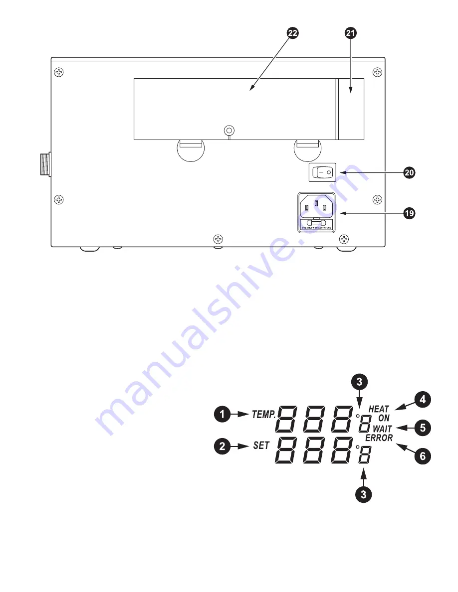
Display and temperature setting
1.
Display for actual temperature of the soldering tip.
2.
Display for set temperature. Turn the “UP”- “DOWN”
knob clockwise to increase temperature and
counter-clockwise to decrease temperature.
3.
°C/°F display: Change the temperature display
from °C to °F by pressing “UP”- “DOWN” knob,
then the electronic system will display the actual
temperature and setting temperature in °C or °F.
4.
When the actual temperature on the soldering tip
is less than the set value, “HEAT ON” will display
when the tip is heating up to maintain the desired
temperature.
5.
When the absolute offset is more than ±10° C between the set value and the actual
temperature on the soldering tip, “WAIT” will display. This means that the temperature
control system detects a non-stable situation. Pause a moment until “WAIT” disappears.
6.
When “ERROR” displays, there may be an issue with the temperature control system, or the
soldering iron is not connected to the station correctly.
Back of unit
4


