background image

 
Chapter Two: 


Introduction to the Front and Rear Panel 


2.1.  Front Display Panel Explanation   
 

2Kva

1Kva

3Kva

Summary of Contents for Tower 1KVA

Page 1: ...Tower 1KVA 2KVA 3KVA True On Line Double Conversion UPS User s Manual 003 2299 Rev A 12 20 2007 ISE Inc 10100 Royalton Rd Cleveland OH 44133 Tel 440 237 3200 Fax 440 237 1744 http iseinc com ...

Page 2: ... Selecting Installation Position 11 3 3 Operation Test and Installation Instruction 12 3 4 Storage Instruction 13 3 5 SNMP Slot 13 4 UPS Working Principle 4 1 When Utility is Normal 16 4 2 When Utility is Abnormal 16 4 3 Overload Condition 17 4 4 Inverter Is out of Order 18 4 5 Inverter Over Temperature 18 4 6 Inverter Over current and Inverter Output Voltage Out of Window 18 5 Troubleshooting Mai...

Page 3: ...s the supply voltage Use a certified input power cable with the correct plugs and sockets for the appropriate voltage system To eliminate any overheating of the UPS keep all ventilation openings free from obstruction and do not store things on top of the UPS Keep the UPS 20 cm away from the wall Make sure the UPS is installed within the proper environment as specified 0 40 C and 30 90 non condensi...

Page 4: ... of battery or batteries in a fire The battery may explode CAUTION Do not open or mutilate the battery or batteries Released electrolyte is harmful to the skin and eyes It may be toxic CAUTION Risk of electric shock battery circuit is not isolated from ac hazardous voltage may exist between battery terminals and ground Test before touching CAUTION A Battery can present a risk of electrical shock a...

Page 5: ...r rating To protect the unit from overloading it automatically switches to bypass mode in case loading exceeds 120 of rating It will automatically switch back to inverter mode once overload condition ceases Should the output becomes short circuited the UPS holds the system and cuts the output automatically till the short circuit situation is removed Should the unit become overheated the internal t...

Page 6: ...er service Guarantees an exclusive protection against DC damage for inductive load such as motor based devices entirely eliminating application limitation Advanced Input PFC control guarantees the PF performance and maximum energy efficiency Unique electronic over current protection detects output short circuit and faults and halts output before damages done to output fuse or equipment thereby min...

Page 7: ...Chapter Two Introduction to the Front and Rear Panel 2 1 Front Display Panel Explanation 2Kva 1Kva 3Kva ...

Page 8: ...mode and vice versa c To illustrate the percentage of output load level at AC Mode and the battery energy level at Backup Mode by pressing the button 4 Fault LED Red LED lights up if UPS is faulty 5 Bypass LED Amber LED lights up when UPS is in Bypass mode 6 Utility LED a AC normal Green LED lights up b 100 for load battery level 7 Inverter LED a Inverter On Green LED lights up b 75 for load batte...

Page 9: ...2 2 1 General Explanation a 120Vac b 230Vac 1Kva 2Kva 3Kva 1Kva 2Kva 3Kva ...

Page 10: ... technician is permitted to proceed with the installation 4 AC Outlet For 120Vac System This is to be plugged by the devices being protected by the UPS Socket type 1Kva 2Kva 3Kva NEMA 5 15R 4ea 4ea 6ea NEMA 5 20R N A 2ea 2ea For 230Vac System Socket Type 1Kva 2Kva 3Kva IEC 320 4ea 6ea 6ea 5 SNMP Slot It is an optional feature used for SNMP card Please Refer to Chapter 3 5 for hardware installation...

Page 11: ... The bundled software of the UPS is for Windows Full function remote control from any computer is via standard RS232 interface using MegaTec s RUPS II protocol 2 3 1 The RS232 interface settings The RS232 interface shall be set as follows Baud Rate 2400 bps Data Length 8 bits Stop Bit 1 bit Parity None 2 3 2 The Pin Assignments of true RS232 type The Pin Assignments of true RS232 type are illustra...

Page 12: ...ccidentally and cause harm to yourself 3 Standard Package includes User s Manual AC Input Power Cord Not available for hard wiring connection models IEC output cables for the UPS with IEC sockets only RJ11 Phone Jack Cable UPS communication kit optional 3 2 Selecting Installation Position It is necessary to select a proper environment to install the unit in order to minimize the possibility of dam...

Page 13: ...rged before usage 1 Make sure the grounding of wall receptacle is properly done 2 Verify if the voltage and frequency ratings match that of Utility then connect the AC Input power cord to a verified grounded 3 wire receptacle 3 Turn on the Main switch on the front panel to start the UPS then the fan on the rear panel will spin 4 After 7 10 seconds the start up Of UPS will be completed then the Uti...

Page 14: ...ute the audible alarm please push the Test Silence Button on the front panel 9 Your installation is done successfully 3 4 Storage Instruction For extended storage through moderate climate the batteries should be charged for 12 hours every 3 months by plugging the UPS power cord into the wall receptacle Repeat this every 2 months under high temperature environment 3 5 SNMP Slot You may install the ...

Page 15: ...S shall be located in a proper location as described in Chapter 3 2 2 Remove the top cover of the UPS Install the SNMP slot kit onto the rear panel of the UPS 3 Insert the SNMP card into the SNMP slot as guided ...

Page 16: ...cover of the UPS back to its position 6 Connect the network cable from the network device ex Hub with SNMP accessibility to the UPS and set the SNMP card to configuration mode and configure the SNMP card Please refer to the user s manual of the SNMP Card for configuration instruction Your hardware installation is now completed ...

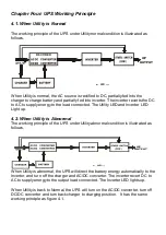
Page 17: ...ight up 4 2 When Utility is Abnormal The working principle of the UPS under Utility abnormal condition is illustrated as follows When Utility is abnormal the UPS will direct the battery energy automatically to the Inverter and turn off the charger and AC DC converter The inverter revert DC to AC to supply energy to the output load connected The Inverter LED lights up When Utility is back to Normal...

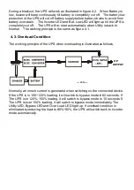
Page 18: ... principle is the same as figure 4 1 4 3 Overload Condition The working principle of the UPS when overloading is illustrated as follows Normally an inrush current is generated when switching on the connected device If the UPS is in 105 120 loading it will switch to bypass mode in 60 seconds If The UPS is in 120 150 loading it will switch to bypass mode in 10 seconds If The UPS is over 150 loading ...

Page 19: ... from damage You shall replace a new fuse with same rating after the short circuit condition is eliminated 4 5 Inverter Over temperature If the UPS experiences over temperature when Utility is normal it will switch to bypass loop The UPS will switch back to inverter mode when the over temperature situation is eliminated If it happens when Utility is abnormal the buzzer will beep continuously and t...

Page 20: ... AC Input cord to wall receptacle 2 Replace the AC fuse with same rating one 3 If problem persists please call for service The UPS switches to battery mode then back to Utility mode when connected device is turned on Or the UPS Switches back and forth between battery and Utility 1 Check if any power strip is connected to the UPS 2 Any damage of Wall Receptacle 1 Do not use power strip 2 Replace th...

Page 21: ...tch to see if the UPS is on again If not call for service UPS is normal but no Output to load Check to see if all cords are properly connected as desired Check all outlets to see if they are properly connected Strange noise and smell Immediately shut down the whole System Disconnect the power from the UPS and call for service 5 3 Maintenance Clean the dust from the ventilation openings and intakes...

Page 22: ...m the installation menu box And give the path of RUPS II system diskette and the designated directory of it You may use the default value of RUPS II 3 The installation program will copy all required files of the RUPS II into the designated path It will also append a Load RUPS EXE Command in your AUTOEXEC BAT file automatically After a complete installation is done the installation program will exe...

Page 23: ...ul loading message on the screen You may switch to the RUPS II Menu by pressing ALT_ESC simultaneously 6 2 2 UPSilon 2000 Installation A UPSilon 2000 for Windows 95 98 NT 1 From the Start Button choose Run 2 Type D Windows Setup exe 3 Choose OK B UPSilon 2000 for Novell Netware V3 1x 1 Login the File Server with access rights in SYS SYSTEM 2 Execute D Netware V3 1x Install exe 3 Re boot System C U...

Page 24: ...e the filename conversion after the ftp File transfer cd tmp mv linux z linux Z or mv LINUX Z linux Z chmod 755 install 4 Execute the installation program install 5 Select a target system from the menu and configure the UPSilon for UNIX Make sure no other process using the same serial port the installation program will launch the UPSilon for UNIX daemon process automatically ...

Page 25: ...ange and corrected within 60ms Synchronization 1 Hz Sec Slew Rate Inverter Free Running If Input Frequency exceeds 3Hz Range Crest Factor 3 1 Transfer Time Line Fault 0 ms Efficiency AC to AC Up to 88 Run Time Full Load 7 Min 7 Min 7 Min DC Start Yes BATTERY Type Sealed Maintenance Free Lead Acid Quantity pcs 3 6 8 Voltage Vdc 36 72 96 Recharge Time 8 Hours To 90 Supplementary Charger Optional 200...

Page 26: ...Conditions PHYSICAL Dimensions WxHxD mm 147x223x401 130x365x479 190x365x453 Net Weight Kgs 15 27 36 Outlets IEC Local Re detailed information please refer to Chapter 2 2 ENVIRONMENT Temperature 0 40 Humidity 90 RH Maximum Non Condensing Noise 45 dB at 1 meter COMPUTER INTERFACE Interface Type Standard RS232 Interface Protocol MegaTec RUPS II SNMP Adaptability Slot for standard SNMP Card kit The st...

Reviews: