background image

6

ELECTRICAL

Ground motor before connecting to electrical power supply. Failure to

ground motor can cause severe or fatal electrical shock hazard.

Do not ground to a gas supply line.

To avoid dangerous or fatal electrical shock, turn OFF power to motor

before working on electrical connections.

Ground Fault Circuit Interrupter (GFCI) tripping indicates an electrical

problem. If GFCI trips and will not reset, have a qualified electrician
inspect and repair electrical system.

Exactly match supply voltage to nameplate voltage. Incorrect voltage

can cause fire or seriously damage motor and voids warranty.
If in doubt consult a licensed electrician.

Voltage

Voltage at motor must be not more than 10% above or below motor name-
plate rated voltage or motor may overheat, causing overload tripping and re-
duced component life. If voltage is less than 90% or more than 110% of rated
voltage when motor is running at full load, consult power company.

Grounding/Bonding

Install, ground, bond and wire motor according to local or National Electrical
Code requirements.
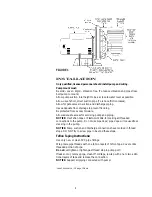
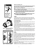
Permanently ground motor. Use green ground terminal provided under motor
canopy or access plate (See Fig. 2); use size and type wire required by code.
Connect motor ground terminal to electrical service ground.
Bond motor to pool structure. Use a solid copper conductor, size No. 8 AWG
(8.4 sq. mm) or larger. Run wire from external bonding lug (see Fig. 2) to rein-
forcing rod or mesh.
Connect a No. 8 AWG (8.4 sq. mm) solid copper bonding wire to the pressure
wire connector provided on the motor housing and to all metal parts of the
swimming pool, spa, or hot tub and to all electrical equipment, metal piping
or conduit within 5 feet (1.5 m) of the inside walls of swimming pool, spa, or
hot tub.

Wiring

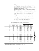
Pump must be permanently connected to circuit. Table I, Page 5, gives correct
wire and circuit breaker sizes for the pump alone. If other lights or appliances
are also on the same circuit, be sure to add their amp loads to pump amp load
before figuring wire and circuit breaker sizes. (If unsure how to do this or if
this is confusing, consult a licensed electrician.) Use the load circuit breaker
as the master on-off switch.
Install a Ground Fault Circuit Interrupter (GFCI) in circuit; it will sense a short-
circuit to ground and disconnect power before it becomes dangerous to pool
users. For size of GFCI required and test procedures for GFCI, see manufac-
turer’s instruction.
In case of power outage, check GFCI for tripping (which will prevent normal
pump operation). Reset if necessary. 
NOTICE: If you do not use conduit when wiring motor, be sure to seal wire
opening on end of motor to prevent dirt, bugs, etc., from entering.

BONDING

LUG

GREEN 

GROUND 

SCREW

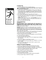
510 0993

A

B

L2

L1

White 

230
Volt

Lines

Blue

SINGLE

VOLTAGE

MOTORS

A

B

L2

L1

White w/

Black

Tracer

Black

230
Volt

Lines

DUAL

VOLTAGE

MOTORS

469 0194

A

B

L2

L1

White w/

Black 

Tracer

Black

115
Volt

Lines

Motor Terminal Board Connections

Hazardous voltage.
Can shock, burn,
or cause death.

Ground pump before
connecting to
power supply.

Figure 2 – Typical ground screw and

bonding lug locations.

Figure 3 – Wiring hook-up diagram.

Summary of Contents for MAX-E-GLAS PE Series

Page 1: ...2G 122 3 PE6H 139L PE62H 139 3 PE6H 139LC PE6H3 139 Sta Rite Pool Spa Group 600 S Jefferson Street Waterford WI 53185 North America 800 752 0183 FAX 800 582 2217 International 414 728 5551 FAX 414 728...

Page 2: ...he Sta Rite PE Series Self priming Centrifugal pump Is designed for use with swimming pools or as a centrifugal pump Is an excellent performer durable reliable Table of Contents Safety Instructions 3...

Page 3: ...BE SURE all air is out of system before operating or testing equipment Before pressure testing make the following safety checks Check all clamps bolts lids and system accessories before testing Releas...

Page 4: ...CE Use Teflon tape or Plasto Joint Stik1 for making all threaded connections to the pump Do not use pipe dope pipe dope will cause stress cracking in the pump NOTICE Pump suction and discharge connect...

Page 5: ...ical Officials IAPMO standards Use only non entrapping suction fitting or double suction TABLE I RECOMMENDED FUSING AND WIRING DATA Serv to Motor Dist in Ft M Motor Branch Fuse Max Load Voltage 0 100...

Page 6: ...mm solid copper bonding wire to the pressure wire connector provided on the motor housing and to all metal parts of the swimming pool spa or hot tub and to all electrical equipment metal piping or con...

Page 7: ...Clean and inspect O Ring reinstall on trap cover Replace trap cover on trap turn clockwise to tighten cover NOTICE Tighten trap cover by hand only no wrenches Use a wrench only if necessary to remove...

Page 8: ...tem Propylene glycol is non toxic and will not damage plastic system components other anti freezes are highly toxic and may also damage plastic components in the system Drain all water from pump and p...

Page 9: ...e 3 Remove clamp holding pump halves together 4 Remove pump base mounting bolts if used Motor and seal plate assem bly can now be pulled away from pump body 5 Remove five screws and washers holding di...

Page 10: ...unterclockwise 8 Mount diffuser on seal plate tighten screws to 10 14 inch lbs 11 5 16 1 cent kg torque 9 Assemble motor and seal plate to volute be sure clamp is properly seated NOTICE Clamp knob can...

Page 11: ...er 7 Make sure impeller is not clogged follow steps 1 through 7 under Removing Old Seal Page 9 check impeller for clogging follow steps 7 through 11 under Installing New Seal Page 10 for reassembly 8...

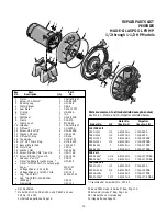
Page 12: ...Clamp Knob 1 WC36 22 10 Impeller 1 Chart at Right 11 Diffuser 1 C1 200PA 12 Screw 8 32x7 8 5 U30 542SS 13 Washer 8 Lock 5 U43 21SS 14 Diffuser O Ring 1 U9 226 15 Tank Body 1 C176 47P1 16 1 4 NPT Drai...

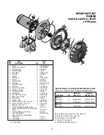
Page 13: ...w 8 32x7 8 5 U30 542SS 13 Washer 8 Lock 5 U43 21SS 14 Diffuser O Ring 1 U9 226 15 Tank Body 1 C176 47P1 16 1 4 NPT Drain Plug 1 U178 920P 17 Base w Motor Pad 1 C104 42P 18 Motor Pad 1 C35 11 19 Washer...

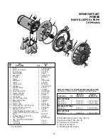
Page 14: ...C30 12 11 Diffuser 1 C1 259P 12 Screw 8 32x7 8 5 U30 542SS 13 Washer 8 Lock 5 U43 21SS 14 Diffuser O Ring 1 U9 226 15 Tank Body 1 C176 47P1 16 1 4 NPT Drain Plug 1 U178 920P 17 Base w Motor Pad 1 C104...

Page 15: ...Capscrew 5 16 18x1 1 4 U30 64SS 4 U30 64SS 4 8 Washer Lock 5 16 U43 11SS 4 U43 11SS 4 9 Washer Flat 5 16 U43 41SS 4 U43 41SS 4 Quantity one unless otherwise indicated Overhaul Kits H P Parts Pak Numbe...

Page 16: ...ence misapplication im proper installation or maintenance or other circumstances which are not in Sta Rite s direct control Full warranty coverage is in effect for one year after instal lation The pro...

Reviews: