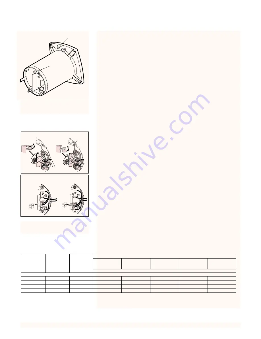
STA-RITE JHSC-61USF Owner'S Manual Download Page 6

Pull plug 
straight
out from 
terminal
board.

1.

1.

2.

2.

Plug in again
with arrow 
on plug 
pointing to
'115 Volts'.

A

L1

2

3

0


V

o

lt

s

1

1

5


V

o

lt

s

A

L1

2

3

0


V

o

lt

s

1

1

5


V

o

lt

s

Ground
Screw

3962 0401 A

115 V

230 V

230 Volt to 115 Volt Conversion. 

Move plug to change voltage.

Ground
Screw

23

0V

11

5V

23

0V

11

5V

A

A

L2

L2

L1

L1

23

0V

11

5V

A

A

L2

L2

L1

L1

23

0V

11

5V

Power Supply 
Wires

230 Volt to 115 Volt Conversion. 

Move plug to change voltage.

Figure 3 – Wiring hook-up 
diagram.

6

Grounding/Bonding

Install, ground, bond and wire motor according to local or National Electrical
Code requirements.

Permanently ground motor. Use green ground terminal provided under motor
canopy or access plate (See Figure 2); use size and type wire required by
code. Connect motor ground terminal to electrical service ground.

Ground wire must be a copper conductor. It should be the same size as the
current-carrying wires to the motor, but not smaller than No. 12 AWG.

Bond motor to pool structure. Use a solid copper conductor, size No. 8 AWG
(8.4 sq. mm) or larger. Run wire from external bonding lug (see Figure 2) to
reinforcing rod or mesh.

Connect a No. 8 AWG (8.4 sq. mm) solid copper bonding wire to the pressure
wire connector provided on the motor housing and to all metal parts of the
swimming pool, spa, or hot tub and to all electrical equipment, metal piping
or conduit within 5 feet (1.5 m) of the inside walls of swimming pool, spa, or
hot tub.

Wiring

Pump must be permanently connected to circuit. See Table I, for correct wire
and circuit breaker sizes for the pump alone. If other lights or appliances are
also on the same circuit, be sure to add their amp loads to pump amp load
before figuring wire and circuit breaker sizes. (If unsure how to do this or if
this is confusing, consult a licensed electrician.) Use the load circuit breaker
as the master on-off switch.

Install a Ground Fault Circuit Interrupter (GFCI) in circuit; it will sense a short-
circuit to ground and disconnect power before it becomes dangerous to pool
users. For size of GFCI required and test procedures for GFCI, see manufac-
turer’s instruction.

In case of power outage, check GFCI for tripping (which will prevent normal
pump operation). Reset if necessary. 

BONDING

LUG

GREEN 

GROUND 

SCREW

510 0993

Figure 2 – Typical ground screw and

bonding lug locations.

TABLE I – RECOMMENDED FUSING AND WIRING DATA - 60 CYCLE MOTORS

DIAMETER IN FEET FROM MOTOR TO METER

BRANCH

0’

101’

201’

301’

401’

MOTOR

MAX. LOAD

FUSE*

TO

TO

TO

TO

TO

HP

AMPERES

RATING

100’

200’

300’

400’

500’

AMPS

WIRE SIZE

SINGLE PHASE - 115/230 VOLT

1/2

9.9/5.0

15/15

14/14

10/14

10/14

6/14

6/12

3/4

13.4/6.7

20/15

12/14

10/14

8/14

6/12

6/12

1

15.3/7.6

20/15

12/14

8/14

6/14

6/12

4/10

1-1/2

19.2/9.6

25/15

10/14

8/14

6/12

4/10

4/10

*A Fusetron is recommended instead of a fuse in any motor circuit.

Summary of Contents for JHSC-61USF

Page 1: ...rica 800 752 0183 FAX 800 582 2217 International 262 728 5551 FAX 262 728 4461 TELEX ITT 4970245 www sta ritepool com Union City TN Delavan WI Mississauga Ont Murrieta CA 2001 Sta Rite Industries Inc Printed in U S A S533 Rev 9 19 01 This manual should be furnished to the end user of this pump its use will reduce service calls chance of injury and will lengthen pump life 3551 1099 ASB ...

Page 2: ...er system 2 Use equipment only in a pool or spa installation 3 Install pump with at least 2 hydraulically balanced main drains equipped with correctly installed screw fastened anti entrapment certified covers See Page 4 4 Trapped air in system can cause explosion BE SURE all air is out of system before operating or testing equipment Before pressure testing make the following safety checks Check al...

Page 3: ... threads with one to two layers of Teflon tape Cover entire threaded portion of pipe Do not overtighten If leaks occur remove pipe clean off old tape rewrap with one to two addi tional layers of tape and remake the connection NOTICE Support all piping connected with pump Piping Use at least 1 1 4 IPS PVC pipe for pump suction Increase size if a long run is needed To avoid strains on the pump suppo...

Page 4: ...fastened covers in place Testing and Certification Suction outlet covers must have been tested by a nationally recognized testing laboratory and found to comply with the lastest ASME ANSI Specification for Suction Fittings For Use in Swimming Pools Spas Hot Tubs and Whirlpool Bathtub Applications Outlets Per Pump see Figure 1 Provide at least two hydraulically balanced main drains with covers for ...

Page 5: ...ked The flow through the remaining main drain s must comply with the latest ASME ANSI Specification for Suction Fittings For Use in Swimming Pools Spas Hot Tubs and Whirlpool Bathtub Applications ELECTRICAL Ground motor before connecting to electrical power supply Failure to ground motor can cause severe or fatal electrical shock hazard Do not ground to a gas supply line To avoid dangerous or fata...

Page 6: ...ectrical equipment metal piping or conduit within 5 feet 1 5 m of the inside walls of swimming pool spa or hot tub Wiring Pump must be permanently connected to circuit See Table I for correct wire and circuit breaker sizes for the pump alone If other lights or appliances are also on the same circuit be sure to add their amp loads to pump amp load before figuring wire and circuit breaker sizes If u...

Page 7: ...Page 10 Draining Pump 1 Pump down water level below all inlets to the pool To avoid dangerous or fatal electrical shock hazard turn OFF power to motor before draining pump 2 To prevent pump from freezing drain the pump body through the drain plug Key No 12 Page 11 Clean pump thoroughly 3 Cap inlet piping after draining to keep water out of the pipes 4 Be sure motor is kept dry and covered Storage ...

Page 8: ...iceman repair wiring as needed 4 Inspect and tighten all watertight connections 5 Open all valves in suction and return piping 6 Remove any winterizing plugs in piping system 7 Drain all antifreeze from system 8 Close all drain valves and replace all drain plugs in piping system 9 Prime pump according to instructions on Page 7 PUMP SERVICE Pump should only be serviced by qualified personnel Be sur...

Page 9: ...ed surface of floating seat with clean cloth 2 Turn seal plate over so seal cavity is up clean cavity thoroughly 3 Lubricate outside rubber surface of ceramic seat with soapy water and press firmly into seal cavity with finger pressure If seat will not locate prop erly in this manner place cardboard washer over polished face of seat and press into seal cavity using a 3 4 socket or 3 4 piece of sta...

Page 10: ...Clogged pipe impeller worn impeller 5 Make sure impeller is not clogged follow instructions under Removal of Old Seal Page 9 check impeller for clogging follow instructions under Installation of Rotating Part of Seal Unit Page 9 for reassembly 6 Impeller may be worn If so order replacement parts from Repair Parts List Page 11 7 Pump may be trying to push too high a column of water If so a higher h...

Page 11: ...3 8 16x1 1 2 Hex Hd 2 U30 76ZP 15 Motor Pad 1 C35 5 Voltage Sticker 115 230 Volts U27 153 Nameplate U33 155 Not illustrated 1 10 11 2 3 4 5 12 12 6 9 7 8 13 15 14 3551 1099 11 REPAIR PARTS LIST 1 2 through 1 1 2 HP Models JHSC 61USF JHSD 62USF JHSE 63USF JHSF 51USF Motor No Impeller Model No HP Key No 1 Key No 9 115 230 Volt JHSC 61USF 1 2 A100CLL C105 92PNX JHSD 62USF 3 4 A100DLL C105 92PMX JHSE ...

Page 12: ...r pur chaser Purchaser only Sta Rite shall have the option to re pair or replace the defective product at its sole discre tion Purchasers must pay all labor and shipping charges nec essary to replace the product covered by this warranty Requests for warranty service must be made through the in stalling dealer This warranty shall not apply to any product that has been subject to negligence misappli...

Reviews: