LED driver configuration
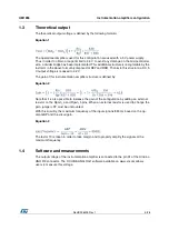
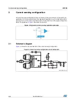
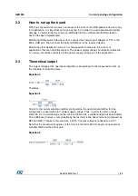
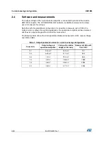
UM1955
14/28
DocID028405 Rev 1
6.2
How to set up the board
There is no specific connection to make the application function, but a PWM input signal is
required on pin D3 of the Arduino UNO R3 connector.
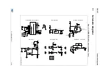
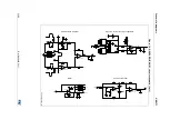
One or several external LEDs in parallel can be added in order to drive several LEDs at the
same time. LEDs can be connected to pin LED_A and LED_K on the expansion board.
Moreover, if needed it is possible to disconnect the mounted LED by removing jumper JP1.
Note also that the supply voltage of the LED can be either external or based on the internal
3.3 V. If several LEDs are in parallel or a higher power is needed, it is recommended to
place the V
cc
jumper in the V
ext
position and use an external power supply.
Depending the PWM duty cycle, the LED intensity will vary. For a duty cycle of 5% (5% of
the time at high state), the intensity will be low. On the other hand, for a 70% duty cycle, the
light intensity will be high.


