Circuit description
UM1943
20/28
DocID028304 Rev 1
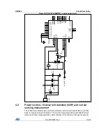
This pin, connected to the STM32 Nucleo board (BKIN Timer function), detects this
condition and immediately disables the driving signals.The current sensing input is
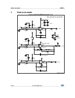
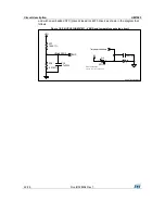
connected to the sensing resistors Rsense (refer to the diagram below) and it is possible to
choose between three-shunt or single-shunt configuration through the jumpers (J5, J6). For
this setting please refer to
Table 1: "Jumper settings"
.
Figure 15: X-NUCLEO-IHM07M1
– current sensing circuit
U
11
L
6
2
3
0
P
D
IN
1
9
C
PO
U
T
24
VSA
4
N.C
.
3
N.C
.
2
G
N
D
1
OUT
3
32
N.C
.
31
V
B
O
O
T
30
E
N
3
29
C
P-
28
V
C
P
7
C
P+
13
N.C
.
14
OUT
1
15
N.C
.
16
N.C
.
17
G
N
D
18
G
N
D
19
N.C
.
20
N.C
.
21
E
N
1
10
SE
N
S1
12
N.C
.
23
N.C
.
6
IN
2
26
SE
N
S2
8
SE
N
S3
25
E
N
2
27
IN
3
11
OUT
2
5
DI
AG
/EN
22
VSB
33
N.C
.
34
N.C
.
35
G
N
D
36
EP
37
OUT
1
OUT
2
J
2
M
o
tor
1
2
3
OUT
3
J
5
C
O
N
3
1
2
3
J
6
C
O
N
3
1
2
3
R
43
0
.33
1W
R
44
0
.33
1W
R
45
0
.33
1W
SE
N
S1
SE
N
S2
3
V
3
SE
N
S3
IN
3
E
N
3
IN
2
E
N
2
R
25
39k
R
26
39k
C
17
1n
F/
6
.3V
R
22
10K
V
s
hun
t_2
E
N
3
IN
3
E
N
2
IN
2
DI
AG
/EN
V
s
hun
t_3
SE
N
S3
V
s
hun
t_2
V
s
hun
t_1
SE
N
S1
V
s
hun
t_2
V
s
hun
t_1
V
s
hun
t_2
V
s
hun
t_3
GSPG14092015DI1540

