UM0509
STPM01 kit components
5/21
2
STPM01 kit components
2.1 Package
checklist
The STPM01 kit package includes the following items:
●
The STPM01 board
●
A CD-ROM with software and documentation
2.2 Debug
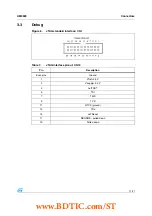
Software debug is via a standard 20-pin JTAG connection.
2.3 Reset
The reset sources are:
●
Power-on reset
●
Push-button reset
●
JTAG reset from an in-circuit emulator
2.4 Power
supplies
Power to the board is supplied using a lump in cord power supply providing 5 V to the board.
All other required voltages are provided by on-board voltage regulators or voltage
convectors.
An isolated 5 V DC/DC provides the isolated voltage supply for the opto-coupler devices.
2.5 Opto-isolated
RS-232
A general-purpose, asynchronous serial I/O data port is connected through 9-pin D-type
male connectors. The port is opto-isolated in order to avoid overvoltage on the PC side.
2.6 SPI
connector
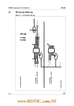
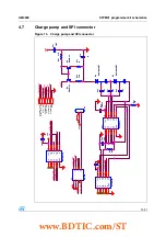
A devoted SPI connector allows interfacing the STPM01 device. It provides all the SPI
signals required to communicate with the STPM01 interface registers. Moreover it provides
a 24 V line which allows burning the STPM01 configuration registers.
www.BDTIC.com/ST


