ST A
UDIO
DSP24 ADAT
- 19 -
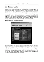
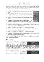
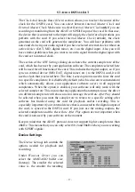
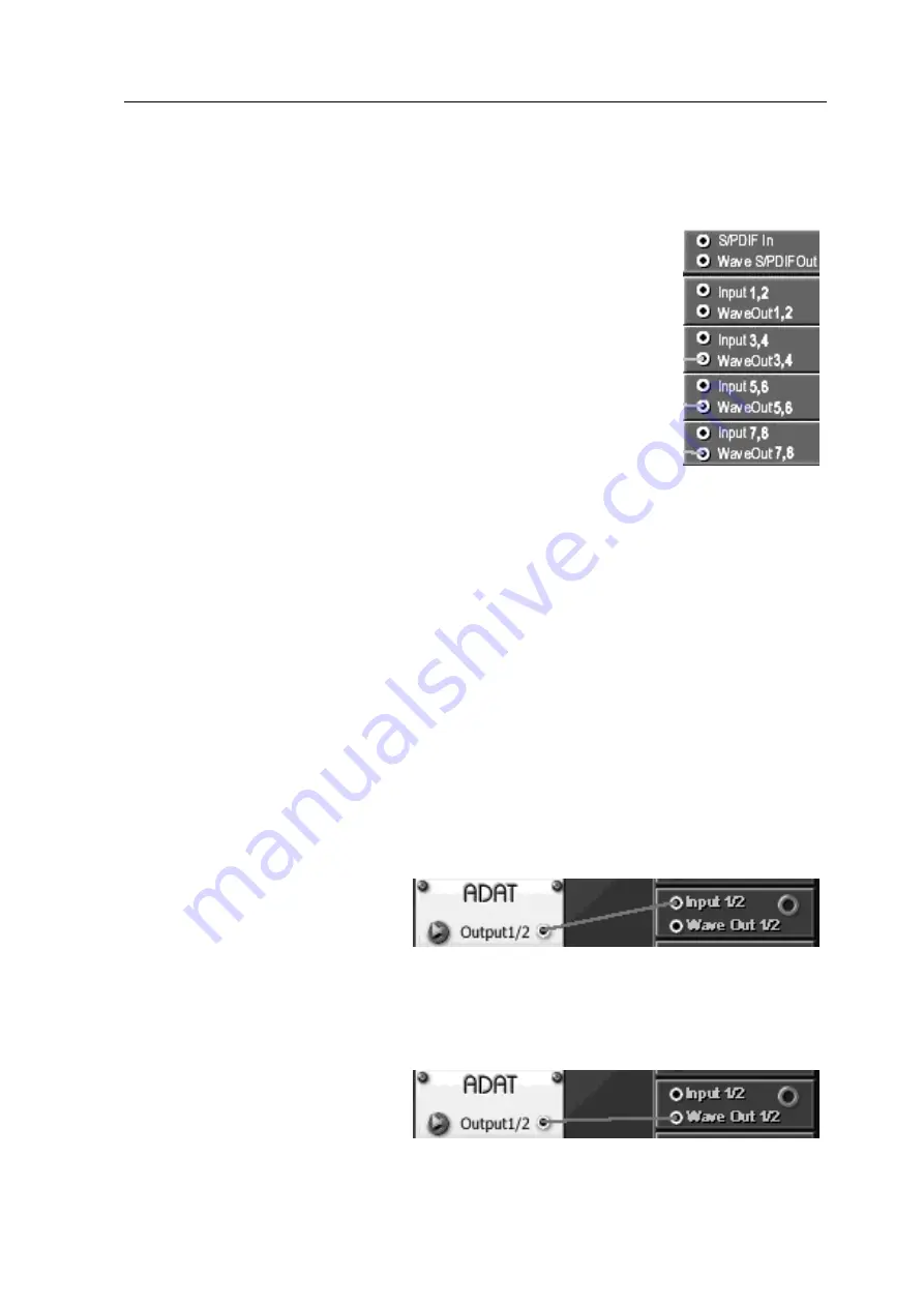
The virtual cables for the outputs (which mainly control the monitoring) cannot be
removed but replaced by other connections. These connections are displayed as
straight lines between the white circles. The available output sources are:
•
S/PDIF In
; the signal from the coaxial S/PDIF input of the
card
•
Wave S/PDIF Out
; the playback of the wave device
ADSP24 S/PDIF Out (n)
or channel 9/10 of the ASIO/GSIF
driver
•
Input 1,2
; the signal from channel 1/2 of the optical ADAT
input
•
WaveOut 1,2
; the playback of the wave device
ADSP24 Ext.
WaveOut 1/2 (n)
or channel 1/2 of the ASIO/GSIF driver
•
Input 3,4
; the signal from channel 3/4 of the optical ADAT input
•
WaveOut 3,4
; the playback of the wave device
ADSP24 Ext. WaveOut 3/4 (n)
or channel 3/4 of the ASIO/GSIF driver
•
Input 5,6
; the signal from channel 5/6 of the optical ADAT input
•
WaveOut 5,6
; the playback of the wave device
ADSP24 Ext. WaveOut 5/6 (n)
or channel 5/6 of the ASIO/GSIF driver
•
Input 7,8
; the signal from channel 7/8 of the optical ADAT input
•
WaveOut 7,8
; the playback of the wave device
ADSP24 Ext. WaveOut 7/8 (n)
or channel 7/8 of the ASIO/GSIF driver
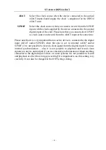
All of these available signal sources can be connected to the outputs on the left side
of the
External Links
window.
Monitoring
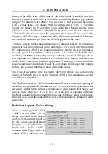
For each stereo channel pair it
is possible to activate direct
monitoring (without any
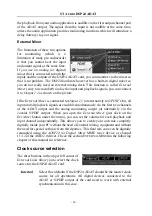
latency). As in the example on these two pictures, you simply do it by connecting
Input 1,2
to
Output 1,2
. This means that the signal from the ADAT input channel
1/2 is sent directly to the output channel 1/2 without any latency / delay. The signal
you play inside your application via channels ½, are not audible now of course!
The second picture shows the
alternative: if you connect
WaveOut 1,2
with
Output 1,2
,

