background image

814-2 

September, 2015 

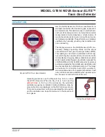
MODEL GT814 NOVA-Sensor 

ELITE™ 

Toxic Gas Detector

TECHNICAL SPECIFICATIONS

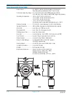
Power Input ........................... 24 volts DC nominal, 80 mA standby, 140 mA alarm.  

Operates within specifications from 16 to 32 volts.

Full scale measuring range ... 10, 20, 50, 100, 200 or 500 PPM (parts per million)  

100, 200, 500, 1000, 2000 or 5000 PPM (high concentration)

Operating Temperature .........

-22 to +122°F (-30 to +50°C) H

2

-4 to +122°F (-20 to +50°C) SO

2

 and CL

2


-4 to +131°F (-20 to +55°C) CO


-13 to +131°F (-25 to +55°C) NH

3


All sensors may be operated intermittently up to +150° F.

Relative Humidity .................. 15% to 90% non-condensing; 0 to 99% intermittently
Ingress Protection: ................

IP40 to IP66. Depends on installed protection options.

Zero Drift: .............................. Less than ±0.1 PPM per month
Sensitivity Drift: ..................... Less  than  2% change per month
T90 Response Time: ............. Less than 20 seconds
Accuracy: ..............................

Linear response 0 to 20 PPM. Full scale error ±6 PPM.

Fuel Cell Life: ........................ 2 years. Plug-in replacement at end of life.
Relay Outputs: ...................... Low Alarm, High Alarm, Malfunction
Relay Contact Ratings: .........

6 amps @ 28 VDC or 300 VAC resistive


1/8 HP @ 120/240 VAC

Analog Output: ......................

0 to 20 mA into a load of 600 ohms or less

Conduit Connection: .............. ¾ inch NPT thread.
Weight: ..................................

6.25 pounds (2.83 kg)

Electronics Enclosure ............

Class I Division 1 Groups B,C,D 

Class I Zone 1 AEx d IIC, IP66  

DEMKO 01ATEX015742U 

II 2 GD Ex dIIC IP66 -20°C to +60°C

Summary of Contents for GT814

Page 1: ...n Manual Installation Operation Maintenance The information and technical data disclosed by this document may be used and disseminated only for the purposes and to the extent specifically authorized by Safety Systems Technology in writing Such information and technical data are proprietary to Safety Systems Technology and may not be used or disseminated except as provided in the foregoing sentence...

Page 2: ...Blank Page ...
Page 3: ...RM RELAY CONTACT FOR LATCHING OPERATION 814 7 10 FOR HIGH CONCENTRATION MODELS ONLY 814 7 ROUTINE OPERATION OF THE NOVA Sensor ELITE 814 8 PROTECTION MODE 814 8 LOW GAS ALARM MODE 814 8 HIGH GAS ALARM MODE 814 9 FAULT MODE 814 9 MAINTENANCE REMINDER MODE 814 9 MAINTENANCE 814 10 MONTHLY BUMP TESTS 814 10 RECALIBRATION SCHEDULE 814 10 RECALIBRATION INSTRUCTIONS 814 11 REPLACING THE ELECTROCHEMICAL ...

Page 4: ...xviii September 2015 Blank Page ...

Page 5: ...hich may be connected to any remote device for remote display or logging Relay contacts are provided which transfer when the gas concentration exceeds the LOWALARM and HIGHALARM set points Typical set points are adjusted by the installer upon installation and may be reset later by authorized personnel The relays are suitable for controlling local HVAC equipment alarm signal devices or for equipmen...

Page 6: ...15 to 90 non condensing 0 to 99 intermittently Ingress Protection IP40 to IP66 Depends on installed protection options Zero Drift Less than 0 1 PPM per month Sensitivity Drift Less than 2 change per month T90 Response Time Less than 20 seconds Accuracy Linear response 0 to 20 PPM Full scale error 6 PPM Fuel Cell Life 2 years Plug in replacement at end of life Relay Outputs Low Alarm High Alarm Mal...

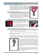
Page 7: ...where a leak is likely or at the highest point within an enclosure Symbol Toxic Gas Density TWA STEL NH3 Ammonia 0 6 25 35 HF Hydrogen Fluoride 0 9 3 Gases with weights near that of air Density of air 1 00 These gases mix readily with air so sensor location is not as critical but sensor should still be near the expected leak point for fastest response Symbol Toxic Gas Density TWA STEL CO Carbon Mo...

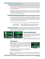
Page 8: ...le from the connector and remove it from the enclosure 3 Mount Sensor Head at a Remote Location optional The toxic gas sensor head that is installed on the bottom port of the enclosure may be re moved and installed at a remote location if desired If the gas sensor head is not to be removed from the Electronics Enclosure skip this section and go to step number 5 below To remove the sensor head disc...

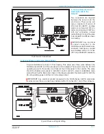
Page 9: ...m of the ELITE enclosure 5 Connect Power and Analog Signal Wiring A typical installation is shown in this drawing This setup uses three wires between the NOVA Sensor ELITE and the associated control modules These wires carry the 24 VDC operating power for the sensor and transmit the 20 mA signal to the controls The wires should be shielded screened or installed in metal conduit to prevent undesira...

Page 10: ...nal pairs LOW ALM LA COM Contact transfers when LOW Alarm setpoint is reached HI ALM HA COM Contact transfers when HIGH Alarm setpoint is reached FAULT FLT COM Contact transfers detector is in a FAULT condition 8 Set Relay Contact Jumpers Jumpers on the detector electronics module lower most circuit board allow relay contacts to be set as normally open or normally closed Low and High Alarm Relay C...

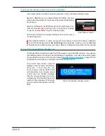
Page 11: ...tches unless you are recalibrating the detector for a different full scale range Refer to Calibration Instructions in this manual 10 For High Concentration Models only For Model GT812 Detectors scaled for PPM values zero to 500 PPM full scale the units are precalibrated and do not need to be recalibrated at installation For units to be used at higher concentrations proceed to the section headed Re...

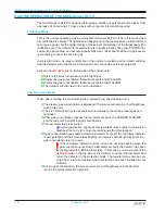
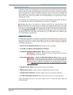
Page 12: ...he detector will then return to normal operation Low Gas Alarm Mode When gas is starting to accumulate in the protected area the following occur The present gas concentration is displayed The screen will remain at half brightness during this time The 4 20 mA signal to external equipment increases to report the present gas con centration When gas concentration reaches the low alarm set point the SC...

Page 13: ...REEN FLASHES and displays SYSTEM FAULT and the yellow FAULT indi cator flashes if failure is not due to power source failed The 4 20 mA signal to external equipment decreases to 2 0 mA or 0 0 mA The fault relay contact to external equipment changes state While in fault mode the NOVA Sensor ELITE might not be able to report an alarm condition The source of fault conditions should be corrected as so...

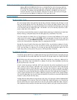
Page 14: ...ector screen You do not need to continue beyond this point you just want to be sure that there is a response If you have test gas with concentrations higher than the alarm trip points you may leave the gas on until they activate if desired Recalibration Schedule The NOVA Sensor ELITE is pre calibrated to the target gas at the factory for measuring ranges up to 500 PPM and no further calibration wi...

Page 15: ...g 50 PPM balance air calibration gas for a 100 PPM toxic gas detector Calibration Procedure The calibration procedure is initiated by activating and holding MagPoint located on the top side of the detector enclosure This will start the sequence of easy calibration instructions displayed on the screen as listed below Messages are as shown below when calibration a 100 PPM H2 S detector 1 HOLD FOR CA...

Page 16: ... minute time out Replacing the Electrochemical Fuel Cell Sensor Element After extended use the sensing element may age to the point where it will no longer be able to calibrate properly This will be indicated by a FAULT after performing a calibration After the sensor fuel cell element has been in service for 2 years the detector will display REPLACE SENSOR CELL as a reminder that the cell is loosi...

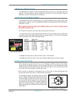
Page 17: ...PM 100 PPM Up Down Down 20 PPM 200 PPM Down Up Down 50 PPM 500 PPM Up Up Down 100 PPM 1000 PPM Down Down Up 200 PPM 2000 PPM Up Down Up 500 PPM 5000 PPM Down Up Up 2 Replace the electronics module and front cover on the detector 3 Recalibrate the sensor head to the new sensitivity following the instructions below Recalibrating the Sensor Head This procedure is required only when you are changing t...

Page 18: ... proper concentration for the new sensitivity The detector will not read your new tar get gas correctly if you do not recalibrate using the specified concentration for calibration gas TROUBLESHOOTING Check Calibration message The sensor head has lost some sensitivity resulting in display values of less then 0 PPM You must perform a recalibration procedure to correct this If the recalibration does ...

Page 19: ...fy the gas concentration near the detector using a personal gas monitor If there is no gas or very little gas recalibrate the NOVA Sensor ELITE If alarms still occur the sensor head has probably lost sensitivity and the detector has tried to compensate by increasing the amplifier sensitivity In that case the sensor fuel cell should be replaced and a new calibration performed Transient Interference...

Page 20: ... have been subjected to an over current are not covered by this warranty For NOVA Sensor ELITE Gas Detectors Electronic Components ONLY Safety Systems Technology Inc SST reserves the right to make the final determination of the nature of and responsibility for defective or damaged equipment Equipment that has been repaired or modified by the user damaged as the result of an accident incorrectly in...

Reviews: