September, 2015
814-13
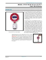
MODEL GT814 NOVA-Sensor
ELITE™
Toxic Gas Detector
Calibrating to a different Target Gas
Your NOVA-Sensor
ELITE
includes internal parts that are specific to the target gas that it
displays. It is not possible to use this detector to monitor for any other toxic gas unless the
detector is returned to the factory for rebuilding.
Changing the Full Scale Maximum Reading
The NOVA-Sensor
ELITE
sensitivity may be changed following the instructions below. After
changing the sensitivity, you must recalibrate the detector sensing head and the NOVA-Sensor
electronics module.
!
Changing the sensitivity without recalibration will result in incorrect readings which
could be unsafe for use.
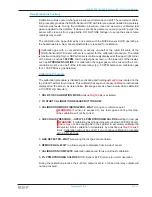
To change the full scale measuring range, follow these instructions.
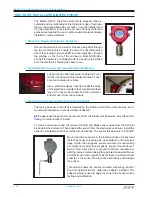
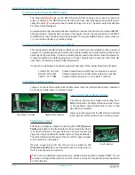
1. Loosen the front cover set screw and remove the front cover. Unplug the electronics mod-
ule and locate the User Options Switch. Option switches number 1, 2 and 3 set the full scale
measurinf range of the Toxic Gas NOVA-Sensor.
Normal
High Conc
Range Range Switch
1 2 3
10 PPM
100 PPM
Up Down Down
20 PPM
200 PPM
Down
Up Down
50 PPM
500 PPM
Up
Up Down
100 PPM
1000 PPM
Down Down
Up
200 PPM
2000 PPM
Up Down
Up
500 PPM
5000 PPM
Down
Up
Up
2. Replace the electronics module and front cover on the detector.
3. Recalibrate the sensor head to the new sensitivity following the instructions below.
Recalibrating the Sensor Head
This procedure is required only when you are changing the PPM sensitivity of the NOVA-
Sensor
ELITE.
Calibration requires access to the potentiometers on the transmitter PC board
located inside the sensor head housing. Loosen the set screw on the cover and unscrew the
cover from the sensor housing to locate these pots.
!
If the sensor is installed in a hazardous area, be sure that no combustible gasses are
present before the front cover is removed from the housing.
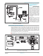
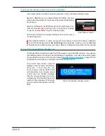
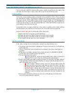
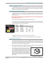
For calibration purposes, the signal must be monitored
using a standard milliammeter inserted into the 4-20
mA circuit. Disconnect the red wire from the PC board
and connect the meter between the red wire and the
open terminal on the PC board. To adjust the potenti-
ometers a small screwdriver is required. Perform the
following procedure to calibrate the sensor/transmitter
combination:
User Options Switch
Transmitter Circuit Board
Summary of Contents for GT814
Page 2: ...Blank Page ...


