background image

O-3000 Camera Series

2.2

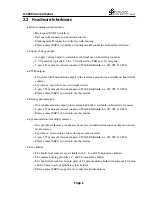
Hardware Interfaces

Main communication interface:

High-speed USB 2.0 interface.

Flat micro-B connector on board-level devies.

Standing mini-B connector on devices with housing.

Please contact SSP if you prefer a standing mini-B connector on board-level devices.

Supply voltage output:

A supply voltage output is available for external use on board-level cameras.

5.0 V nominal, typically 4.5 to 5.5 V delivered by USB host, 50 mA peak.

5-pin, 1.25 mm male vertical connector (Würth Elektronik, no. 653’005’114’822).

PWM outputs:

Two pulse width modulation outputs (plus reference ground) are available on board-level
cameras.

Typical use: control of one or two light sources.

5-pin, 1.25 mm male vertical connector (Würth Elektronik, no. 653’005’114’822).

Please contact SSP if you wish to use this feature.

Flash synchronization:

One synchronization output (plus reference ground) is available on board-level cameras.

5-pin, 1.25 mm male vertical connector (Würth Elektronik, no. 653’005’114’822).

Please contact SSP if you wish to use this feature.

Synchronization of multiple cameras:

One pin (plus reference ground) can be used as synchronization input or output on board-
level cameras.

Typical use: stereoscopic vision, stereopsis, camera arrays.

2-pin, 1.25 mm male vertical connector (Würth Elektronik, no. 653’002’114’822).

Please contact SSP if you wish to use this feature.

Lens holder:

The board-level cameras are available with C-, S- and CS-mount lens holders.

The camera housing provides a C- and CS-mount lens holder.

The board-level cameras feature pairs of 2.1 mm mounting holes with distance 20.0 mm
and 22.0 mm to accept proprietary lens holders.

Please contact SSP for support or for other lens holder options.

Page 6

Summary of Contents for O-3000 Series

Page 1: ...E Mail cam stettbacher ch O 3000 Camera Series User s Guide Version 2 10 2015 08 10 Abstract This user s guide highlights the camera features and gives an overview over the device s basic functions I...

Page 2: ...Interest 4 2 1 4 Frame Rate 4 2 1 5 Exposure Adjustments 4 2 1 6 White Balance 5 2 1 7 Mirroring 5 2 1 8 Data Format 5 2 1 9 Downsampling 5 2 2 Hardware Interfaces 6 2 3 Software Interfaces 7 2 3 1 D...

Page 3: ...functional features of the O 3010 monochrome and the O 3020 color devices in more detail More devices will follow 2 1 Functions This chapter focuses on the camera s main functionalities and on how to...

Page 4: ...of interest e g to reach higher frame rates To set a particular region use the window command described in 6 2 1 4 Frame Rate You can choose a frame rate However note that the frame rate may affect th...

Page 5: ...oring mode allows you to flip the picture up down or left right It can be done by changing values of parameter mirroring For more information please see 6 2 1 8 Data Format The camera is supporting th...

Page 6: ...822 Please contact SSP if you wish to use this feature Flash synchronization One synchronization output plus reference ground is available on board level cameras 5 pin 1 25 mm male vertical connector...

Page 7: ...ht API to communicate with the O 3000 camera series It abstracts user applications from the USB internas and deals with low level interfacing which is tedious to implement and hard to debug if done th...

Page 8: ...en in Java which is connected through several layers to the camera All modules described are part of the driver package We will come to that later on in section 3 2 Basically the top layer application...

Page 9: ...rts to illustrate a working example and can be modified under terms of GPL and LGPL The O 3000 camera driver binaries and C sources A Demo Application an implementation of a GUI software for this came...

Page 10: ...later 4 Stettbacher Signal Processing 2013 O 3000 Camera Series Camera Driver Package Documentation Stettbacher Signal Processing version 1 20 2013 05 24 5 Stettbacher Signal Processing 2013 O 3000 Ca...

Reviews: