


2.2 Front Panel Control
25
2.2
Front Panel Control
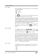
The SR542 front panel is organized into seven functional blocks which
are described in this chapter: Numeric Display, Configuration, Dis‑
play/Adjust, Phase, Numeric Entry, Motor, and Setup. The front panel
is shown in Figure 2.8.
Stanford Research Systems
Model SR542
Precision Optical Chopper
Run
Stop
Source
Control
Multiplier
×—
× 1
n
m
Ext Sync
Locked
AC Line
VCO Input
Internal Freq
0 to +10Vdc
Chopper Locked
Chopper Unlocked
Outer
Inner
Shaft
Hold button for
secondary function
– P
ha
se
+
Ro
ta
tio
n
Push to adjust
Hold to Run
Slot count
Clear ERR
Display ERR
USB
ERR
Hz
deg
Multiplier
Rel
Outer Slots
Inner Slots
Int Freq
Phase
VCO FS
n
m
Frequency Monitor
Settings
Shaft
Source
Motor
Source
Control
Rel
Phase
Run /
Stop
Edge
Save
Recall
Back
Int
Shaft
0
1
2
3
4
5
6
7
8
9
.
±
Cancel
Pending
Figure 2.8:
The SR542 front panel.
2.2.1
Power
The
button is used to turn the SR542 controller On and Off.
2.2.2
Numeric Display
At the top left of the front panel is a 6‑digit numeric display which
displays the parameter indicated by the
Frequency Monitor
or
Settings
LEDs.
Frequency Monitor
selections display frequencies
measured
by the
control unit, while
Settings
selections display variables that can be
set
by the user. Units are indicated according to the displayed parameter
(
Hz
,
deg
,
Multiplier
, or
Rel
), and if the parameter is signed, the
appropriate sign LED will light.
In the top right corner of the numeric display are indicators for remote
interface activity (
USB
) and errors present in the error buffer (
ERR
).
For more information on the error buffer, see Section 3.6.
SR542 Precision Optical Chopper


