


2.2 Front Panel Control
33
2.2.8 Setup
The
SETUP
block consists of buttons that allow the user to save and
recall instrument configurations to and from non‑volatile memory loca‑
tions as well as to jump back to the previous configuration.
Table 2.1:
Configuration settings that are saved
(recalled) to (from) non‑volatile memory. The fac‑
tory default values can be recalled from Loc 0.
Setting
Default Value (Loc 0)
Source
Internal Freq
Edge
Rising
Control
Outer
Int Freq
100 Hz
Phase
0.00 deg
Rel Phase Enabled
False
Multiplier,
𝑛
1
Divisor,
𝑚
1
VCO FS
100 Hz
2.2.8.1
Save
The
Save
button is used to save the current configuration to a non‑
volatile memory location. There are 9 available memory locations for
user configurations, which can be saved in locations 1, 2, 3,… 9.
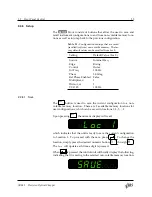
Upon pressing
Save
, the numeric display will read:
±8.8.8.8.8.8.
Loc 1
which indicates that the unit is ready to save the current configuration
to Location 1. To proceed with the save, press
. To change the
location, simply press the desired numeric button,
1
through
9
.
The
Loc
will update each time a digit is pressed.
When
is pressed, the control unit will briefly display the following,
indicating that it is saving to the selected non‑volatile memory location:
±8.8.8.8.8.8.
SAVE. . .
SR542 Precision Optical Chopper


