


20
2 Operation
2.1.2 Chop Mode
Chop mode refers to the standard use case of an optical chopper in
which the motor runs at a steady rate in order to provide a chopped
optical signal with the appropriate frequency and phase.
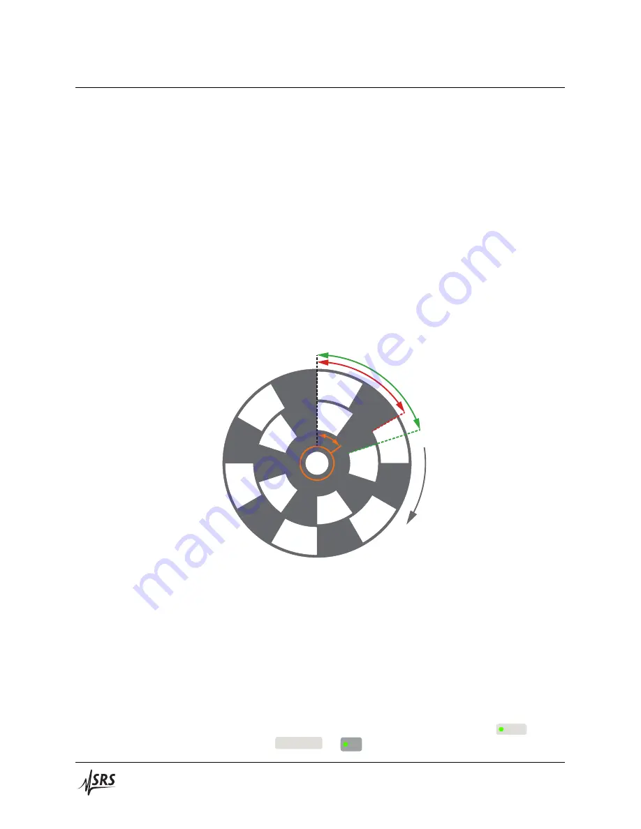
It is instructive to consider in detail the meaning of phase under var‑
ious instrument configurations. For all of the following examples, we
use the O54256 5/6 slot dual‑frequency blade, with the shaft encoder in‑
dex position arbitrarily oriented at +54
°
mech relative to the coincident
inner and outer track edges, as depicted in Figure 2.2. The shaft encoder
produces a once‑per‑revolution pulse (output high), with a duration of
1/400
th
of a mechanical revolution, as the index position rotates through
the encoder’s optical sensor. The pulse is available at at
Rotor Shaft Ref
Out
.
For a chopper blade track with
𝑛
slots
, a mechanical rotation of 360
°
mech/
𝑛
slots
produces a full 360
°
opt cycle.
Outer: 360°opt
= 60°mech
Inner: 360°opt
= 72°mech
54°mech
Rotation
Figure 2.2:
Relationship between optical and mechanical degrees (
°
opt and
°
mech) for O54256 5/6 slot dual‑frequency blade. Positive rotation of the chop‑
per blade is clockwise when viewed from the front of the chopper head. The
shaft encoder index orientation (which is
not
a feature of the chopper blade
itself, and will generally vary for any given chopper head unit) is shown in
orange. For ease of comparison to the timing diagrams below, the index orien‑
tation is measured relative to the coincident edges of the inner and outer tracks
(leading by +54
°
mech in this example).
2.1.2.1
Shaft Control
First consider the instrument configuration and timing diagram of Fig‑
ure 2.3, in which the SR542 is configured to control the
Shaft
, with a
frequency
Multiplier
of
×
1
. The
Rotor Shaft Ref Out
(one‑pulse‑per‑
SR542 Precision Optical Chopper


