


2.1 Functional Overview
21
revolution) is frequency‑locked to the
Source Output
waveform, with a
Phase
setting of 0
°
. With the O54256 5/6 slot dual‑frequency blade, the
Inner Slots Ref Out
produces a waveform at
5 × 𝑓
shaft
, and
Outer Slots Ref
Out
at
6 × 𝑓
shaft
. The systematic phase offset
𝜙
shaft
− 𝜙
blade
(54
°
mech in
this example) between
Rotor Shaft Ref Out
and the
Inner/Outer Slots Ref
Out
signals exists due to the installed orientations of the shaft encoder
and chopper blade.
Source
Shaft
Inner (N=5)
Outer (N=6)
Edge
CONFIGURATION
×1
Multiplier
Control
T
Source
= T
Shaft
T
Source
φ
Shaft
- φ
Blade
Shaft
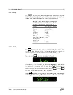
Figure 2.3:
Simulated timing diagram of rear‑panel outputs for
Shaft
control
with 0
°
phase offset. Width of
Rotor Shaft Ref Out
pulse is exaggerated for
illustrative purposes.
The next example, shown in Figure 2.4, is identical to Figure 2.3 except
that a ‑90
°
phase offset has been added by programming the
Phase
set‑
ting available to the user. The sign of this phase offset indicates that the
controlled track will
lag
the Source by 90
°
.
2.1.2.2
Blade Control: Inner Slots
If the
Control
is changed to
Inner
, then the
Inner Slots Ref Out
will be
frequency and phase‑locked to the
Source Output
as is shown in Fig‑
ure 2.5. As shown by the block diagram in Figure 2.1, the chopper is
always controlled using the shaft encoder signal (with a phase and fre‑
quency appropriately scaled by
𝑛
slots
, the number of slots of the selected
Control
track). For control of
𝑛
slots
= 5
, the shaft frequency will be
locked to
𝑓
source
/5
. Together with a phase setpoint of 0
°
, this will result
1
The blade feature corresponding to coincident falling edges of the Inner and Outer
reference signals was chosen as an easy‑to‑recognize reference point from which to
measure the shaft offset. This offset depends on the factory‑installed shaft encoder
orientation and the user‑installed blade orientation, and in general will vary from
54
°
mech. Furthermore, due to lateral offsets of the opto‑interrupters which produce
Inner Slots Ref Out
and
Outer Slots Ref Out
, the phases of the Inner and Outer signals
will be shifted slightly in comparison to the simplified timing diagrams shown here.
SR542 Precision Optical Chopper


