background image

Ranger S  Installation and troubleshooting

29

Configuring for Flow Sensor Input

In the previous section you enabled the Ranger 4000 S to accept flow 
sensor input ‐ now you need to configure what to do with it and this section 
walks you through the relevant procedures.

Selecting Sensor Type

By telling the Ranger 4000 S which type of sensor you are using, the 
controller can calibrate the input it receives from the input terminals. The 
Ranger 4000 S knows the calibration profiles for 12 different sensor types 
‐ if you're not using one of these you'll have to skip to the next procedure 
to perform a manual calibration for your sensor.

Using a known sensor type to enable a built‐in profile:

Using a built‐in calibration profile

1 Turn the dial to 

ADVANCED

, use the 

item selectors 

to scroll to item 

number 

3. FloGuard

, and push the 

ENTER


button.

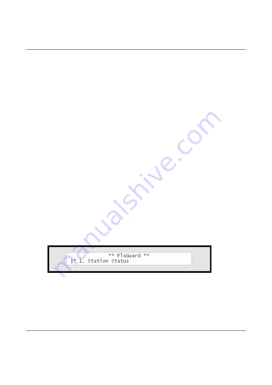
Now you'll see this display:

Summary of Contents for RANGER 4000 S

Page 1: ...Ranger S Installation and troubleshooting 1 RANGER 4000 S SRC IRRIGATION CONTROLLERS INSTALLATION TROUBLESHOOTING MANUAL...

Page 2: ...2018 All rights reserved No part of this publication may be reproduced stored in a retrieval system or transmitted in any form or by any means electronic mechanical photocopying recording or otherwise...

Page 3: ...ET and Rain figures 15 Connecting a Rain Sensor 17 Configuring for a Rain Sensor 19 Setting Hourly Maximum Rain and Rain Alarm Level 23 Setting the Hourly Max Rain and Rain Alarm Level 24 Connecting a...

Page 4: ...a soil moisture sensor 39 Chapter 3 System activation 43 Station license 43 Moisture license 45 Chapter 4 Troubleshooting from the Controller 47 Testing Stations 47 Enabling current readings 47 Runnin...

Page 5: ...atures Here are the main features that the Ranger 4000 S utilizes to help you automate your irrigation Controls up to 100 solenoids attached to valves or relays via the built in connection board and t...

Page 6: ...a 14 day period or on odd even dates You can activate one or more valves or programs manually while one or more programs are running up to a total of 12 simultaneously running valves A master valve c...

Page 7: ...nect all cables to the controller at the location To minimize electromagnetic interference make sure that the controller is placed at least 4 5 m away from any high draw motors like air conditioners r...

Page 8: ...ontroller Grounding the Controller To secure your Ranger 4000 S against lightning you must ensure that the controller is grounded through a ground rod connected to the ground lugs Warning You will voi...

Page 9: ...troubleshooting 7 The power distributor The power distributor delivers 24VAC to the controller and to various AUX connections It also has a power switch 24VAC in 24VAC out 24VAC out Power switch 24VAC...

Page 10: ...er just lets an external device tell it when to irrigate and when to stay passive In this mode the controller supports two ET devices WR 7 and WR100i To make the controller receive instructions from a...

Page 11: ...the ET device will monitor the exact weather condition right where irrigation will take place ET GND Rain GND Flow GND V Aux GND MV BO1 BO2 NOM COM COM M204 M203 M202 M205 Important Be aware of the p...

Page 12: ...weather stations fails and does not provide any input for the Ranger 4000 S the controller will fall back on historical ET data and use these instead The same goes in case of a power failure the cont...

Page 13: ...ee the following screen 4 Select 6 Device Setup Now the display will look like this 5 Select 1 ET Input Method Now the display will look like this 6 Use the item selectors to select Local Weather Stat...

Page 14: ...10 Use the item selectors to select 2 ET Limits Min and Max and push the ENTER button Now you ll see the following screen 11 Now use the item selectors to determine the two values and push ENTER to sa...

Page 15: ...roubleshooting 13 12 Turn the dial to SETUP SENSORS Now the display looks like this 13 Use the item selectors to select 1 ET and push the ENTER button Now the display looks like this 14 Now you can ch...

Page 16: ...losed N C Whenever the device is then in the opposite mode the controller will hold its irrigation Disabled Don t use the ET input Use the item selectors to locate the setting you want and if you chos...

Page 17: ...ct 3 Intelliset and push the ENTER button Now you ll see the following screen 17 Select 6 Device Setup Now the display will look like this 18 Select 2 ET and Rain Inch Pulse Settings Now you ll see so...

Page 18: ...ain has fallen or how much water has evaporated the Ranger 4000 S has a screen that shows you the accumulated values in real time Reading current aggregated ET and Rain figures 1 Turn the dial to ADVA...

Page 19: ...If you use a custom irrigation period this happens at the start of your irrigation period which might not be midnight See more in the Ranger 4000 User Manual Tip If you are running in AUTO mode and wa...

Page 20: ...it rains at all works with sensors and tipping rain bucket Stop irrigating if the rain level exceeds a certain threshold works with sensors and tipping rain bucket Adjust irrigation based on the amoun...

Page 21: ...Configuring for a Rain Sensor 1 Before moving on make sure you have connected the rain sensor For more information refer to the separate Installation and Troubleshooting manual 2 Turn the dial to SETU...

Page 22: ...select Pulses Rain contact N O or N C If your rain sensor simply tells the controller whether to irrigate or not if it s raining or not you need to tell the controller if the input is normally open or...

Page 23: ...h pulse corresponds so please continue to the next step 5 Turn the dial to ADVANCED Now the display looks like this 6 Use the item selectors to select 3 Intelliset and push the ENTER button Now you ll...

Page 24: ...ect 6 Device Setup Now the display will look like this 8 Select 2 ET Rain Setup and then 2 ET and Rain Inch Pulse settings Now you ll see something like this 9 Use the item selectors to set your value...

Page 25: ...data the controller will calculate how much rain will evaporate and mapping this number against the known amount of fallen rain the controller will intelligently know when it is safe to turn off the r...

Page 26: ...hourly maximum Example If the hourly maximum is 5 mm and it rains 6 2 mm per hour for three hours only 15 2 mm and not 22 8 mm will be subtracted from tomorrow s ET budget See more in the Ranger 4000...

Page 27: ...ook like this 4 Select 3 Max Hourly Rain and Rain Alarm Limit from the menu and push the ENTER button Now you ll see the following screen Note Setting a value to zero is the same as disabling the feat...

Page 28: ...he ENTER button to save your settings Connecting a Flow Sensor A traditional flow sensor is connected to the Flow terminals Note Be aware that testing the tipping rain bucket input by flipping the spo...

Page 29: ...Watt 12V 470 Ohm 0 5 Watt Enabling Flow Sensor Input pulses By default flow sensor input is enabled in the Ranger 4000 S To enable flow sensor input to accept pulses follow this procedure Enabling fl...

Page 30: ...3 Alarm Flow and you ll see the default setting for sensor setup Flow Pulses 3 Push the ENTER button to save your selection Now the Ranger 4000 S is ready to accept input from your flow sensor but be...

Page 31: ...ensor you are using the controller can calibrate the input it receives from the input terminals The Ranger 4000 S knows the calibration profiles for 12 different sensor types if you re not using one o...

Page 32: ...item selectors to select one of the 5 built in profiles Data Industrial Badger Meter 250BR10 Data Industrial Badger Meter 228PV15 Data Industrial Badger Meter 228PV20 Data Industrial Badger Meter 228P...

Page 33: ...ow you ll see this display 3 Use the item selectors to locate the Custom option and select it by pressing the ENTER button Now you ll see the calibration screen Note A bit of background on how calibra...

Page 34: ...n to save your settings Setting the Flow Sensor Adjustment If you want to calibrate your flow sensor you can use the sensor adjustment to multiply the values from your sensor with anything between 0 0...

Page 35: ...nsor Adjustment Now you ll see the screen for adjusting the flow sensor input 4 Use the item selectors to set your adjustment factor Push the ENTER button to save your selection Viewing the Current Fl...

Page 36: ...e the current system flow in both pulses per second and liters per minute Note The Ranger 4000 S can measure correctly up to a flow of 250 pulses per second If your flow exceeds this you should use a...

Page 37: ...Alarm The grey terminals labeled AUX are intended for a regular auxiliary alarm ET GND Rain GND Flow GND V Aux GND MV BO1 BO2 NOM COM COM M204 M203 M202 M205 Note An alarm is used instead of a Flow Se...

Page 38: ...es how you actually get the moisture sensors ready for use and how they can improve your irrigation The Ranger works with the following moisture sensors AquBlu SRC Moisture Probe30 SRC Moisture Probe5...

Page 39: ...tributor and perform some basic configuration Follow this procedure to get your moisture sensor up and running Assigning an ID to a soil moisture sensor 1 Connect the soil moisture sensor to the RS232...

Page 40: ...sture Sensor Id Assign and push the ENTER button Now the display looks like this 5 Select 4 Moisture Sensor Id Assign and push the ENTER button Now the display looks like this The number of sensors av...

Page 41: ...nd the controller moves on to detect the new sensor If all goes well you will see the following message in the display Once your moisture sensor has an ID you need to tell the controller what type of...

Page 42: ...eshooting 40 Now the display looks like this 2 Use the item selectors to select 3 Intelliset and push the ENTER button Now you ll see the following screen 3 Select 2 Moisture and push the ENTER button...

Page 43: ...ure For more information turn to Capter 2 Assigning an ID to a soil moisture sensor on page 37 and then adjust each column Column Description Enable Whether the moisture sensor should be enabled or no...

Page 44: ...h the ENTER button to save your configuration 7 Repeat steps five and six for all sensors you wish to configure Now the moisture sensors are ready to use and the next sections go into detail on how yo...

Page 45: ...ou have purchased a license that allows for more stations and to unlock the Ranger 4000 S to control all your licensed stations follow this procedure Station license 1 Turn the dial to Advanced Note T...

Page 46: ...r ID will be different Note To obtain a license key for more stations you need to know the ID you see in this display keep this ready when ordering 3 Press the ENTER button once and the first license...

Page 47: ...ms with all your licensed stations right away 4 After pressing any key to continue you will be back at this display Moisture license 5 Repeat 1 og 2 If you have a license for moisture sensors push the...

Page 48: ...Ranger S Installation and troubleshooting 46 If your license code is correct you will see a message like the following In this case the license is valid for three moisture sensors...

Page 49: ...es the various ways you can troubleshoot your controller and stations Enabling current readings The most important tool in day to day troubleshooting is the built in current readings To enable current...

Page 50: ...see the line status in the upper right hand corner Note The display will return to showing the time if you power down the controller The current reading will toggle between current readings for the i...

Page 51: ...to check if they are responding correctly The stations must be connected to the solenoids that activate valves in the landscape and the test can tell whether the stations and solenoids are working cor...

Page 52: ...is ok since this is typically in the 200 400 mA range If the station fails the display will look something like this If the station is not working correctly it is typically not pulling any current at...

Page 53: ...k through the landscape and ensure that all stations are actually pulling the valves open Running the test program 1 Turn the dial to MANUAL Reading Meaning 1mA 1mA There is a short on the terminal on...

Page 54: ...e time each valve should be pulled open and which station you wish to start from The interval must be between 10 and 990 seconds Once you ve set the interval time push the ENTER button to start the te...

Page 55: ...Note All 100 station identities will activate in turn this means that if you don t have connected stations to all slots in the connection boards you will experience empty intervals where no stations...

Page 56: ...gram out just to see that everything activates in the right order you can decrease the water budget to 1 percent before running the program This way you can follow the program by walking from station...

Page 57: ...Ranger S Installation and troubleshooting 55 Glossary Term Description Cable Two wires surrounded by insulation Two wire Synonym for a cable Wire An individual copper wire...

Page 58: ...Ranger S Installation and troubleshooting 56...

Page 59: ...Ranger S Installation and troubleshooting 57...

Page 60: ...Ranger S Installation and troubleshooting 58...

Reviews: