background image

1008290 Rev. C

7

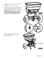
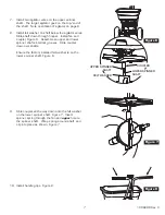
7.  Install two agitator wires on the upper spinner 

shaft.  The larger agitator goes on the top/end of 
the shaft.  Note orientation of agitator on page 9.

8.  Install felt washer on shaft below the agitator wires.  

Slide shaft down through hopper.  Install fan and 
coupler, Figure 6.  Assemble so upper and lower 
spinner shafts interlock grooves.  Slide coupler 
down over shafts.


Ensure the factory installed felt washer is on the 
lower spinner shaft, Figure 6.

COUPLER

UPPER SPINNER

SHAFT

FELT WASHER

LOWER SPINNER
SHAFT

9.  Slide coupler all the way down onto the felt washer 

on the lower spinner shaft, Figure 7.  Insert 
spinner spring through the fan and 

upper

 hole on 

the spinner shaft.  Wrap spring around shaft  and 
clip into place as shown, Figure 7.

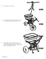
10.  Install handle grips, Figure 8.

Figure 6

Figure 7

Figure 8

Summary of Contents for S60-12020

Page 1: ...rinly Hardy Co Model S60 12020 Spyker Spreaders Contact Us at 800 972 6130 This manual contains information for the safety of persons and property Read it carefully before assembly and operation of th...

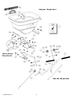
Page 2: ...C 2 63 68 27 61 60 61 27 74 74 28 26 71 71 21 62 55 54 28 74 30 43 53 52 34 35 22 38 56 40 4 40 46 45 47 44 48 26 50 41 27 51 49 42 33 57 37 36 74 25 23 39 Rate Gate Explosion Hopper Explosion Handle...

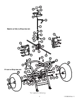
Page 3: ...12 20 17 5 6 24 1 72 64 65 66 73 19 16 8 7 9 18 16 7 11 15 13 10 As needed for shimming 10 74 67 68 31 74 29 32 2 77 68 3 3 70 74 3 2 27 27 68 68 67 70 3 59 70 59 76 75 69 10 10 29 Frame Explosion Spi...

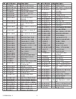
Page 4: ...8 Bolt HexHd 1 4x1 2 SS 36 1008250LH 1 Brace Hopper LH 37 1008250RH 1 Brace Hopper RH 38 1008271 1 Hopper 120 Drilled No Part Number Qty Description 39 05 94 0064 6 Washer Nylon 40 05 90 0121 4 Bolt...

Page 5: ...t On the drive wheel side install 3 16 x 1 3 4 Clevis Pin and Cotter Pin Figure 1 On opposite side install wheel washer and Rue Ring Locking Pin on outside of wheel NOTE Extra wheel washers are provid...

Page 6: ...mbly sideways and insert end of linkage into rate gate linkage Figure 4 6 Install handle to frame as shown using 1 4 x 1 3 4 Bolts and Locknuts NOTE You ll need to orient and install the cable bracket...

Page 7: ...and lower spinner shafts interlock grooves Slide coupler down over shafts Ensure the factory installed felt washer is on the lower spinner shaft Figure 6 COUPLER UPPER SPINNER SHAFT FELT WASHER LOWER...

Page 8: ...ng that can get caught in moving parts Always wear eye protection when operating the equipment Stay alert for holes in the terrain and other hidden hazards Watch out for traffic when crossing or near...

Page 9: ...dge Of Spread lines Gaps and double overlaps are less likely Small errors in travel are forgiven and do not show WARNING When spreading products containing herbicides exercise extreme caution with res...

Page 10: ...spread Make the first spread pass at one half the spread width from the edge of the spreading area or in this case approximately 3 feet or one big step Additional spreading passes will be at the full...

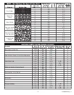
Page 11: ...ADING CHART Product Bag Weight Sq Ft Coverage Dial Setting Full Rate Dial Setting Half Rate Spread Width Blue Grass or Red Top 5 lbs 1 000 1 25 4 1 lbs 1 000 2 0 4 2 lbs 1 000 2 5 4 Park Merion Delta...

Page 12: ...l not be liable for any loss damage or expense including but not limited to consequential or incidental damages arising from the operation condition or use of the item The sole and exclusive remedy ag...

Reviews: