SPIDAR Software
47
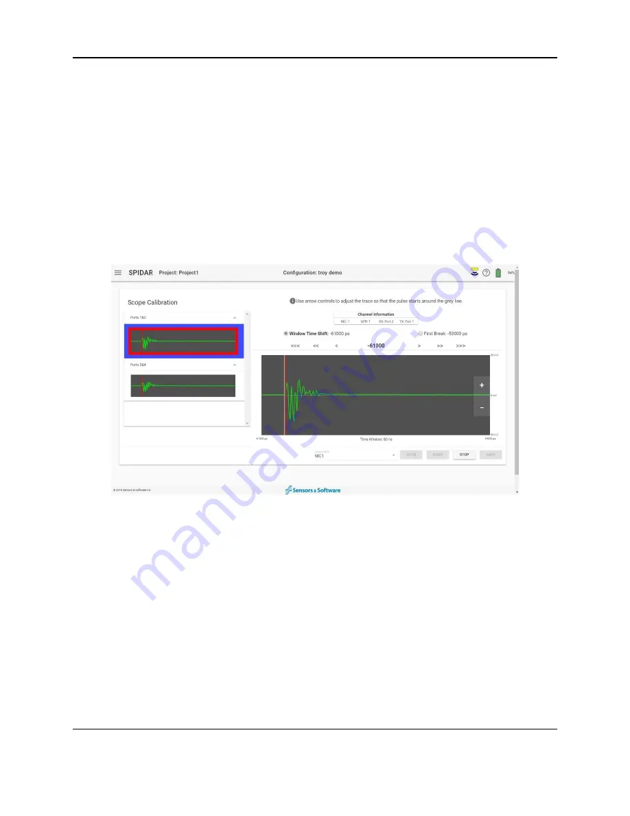
with the associated channels. The Window Time Shift is set for the selected Ports, framed by a
blue border, and the First Break is set for the selected channel, framed by a red border. If there
is more than one NIC-500, select the first NIC-500 from the drop-down menu at the bottom of
the screen
At the t
op of the screen is an icon with the letter ‘i’ in a circle. The text beside this icon displays
useful information about what is happening at each step, and which channels it’s affecting.
Below that
is a dialog box titled “Channel Information”; this describes the details for the
transmitter-receiver pair currently being scoped.
On the main scope window, the + and
– buttons can be used to zoom in and out on the vertical
scale. Below this window, the Time Window value is displayed. The maximum Time Window
that can be displayed in Scope Mode is 500ns, even if the actual Time Window is longer.
Despite seeing a shorter time window, the entire time window is still being scoped.
Figure 4-30: Scope mode for NIC-500P
Auto
is generally the preferred method of setting both the Window Time Shift and First Break.
Use
Start
to skip the automated search and set Window Time Shift and First Break manually.
Note: Auto may fail if high frequency transducers are being employed, the antenna separation is
large, or there is a large amount of external noise. In that case, try raising the antennas or
transducers slightly off the ground to allow a stronger air wave to travel between the units.
For the NIC500-P (Figure 4-30):
1. Select Ports 1&2.
2. Press Auto. The system will initiate a search to attempt to set the Window Time Shift and
the First Break for Ports 1&2.
3. If there is a need to manually adjust, select the radio button for Window Time Shift or
First Break and use the arrows above the scope window to adjust their positions. More
Summary of Contents for SPIDAR NIC-500s
Page 1: ......
Page 2: ...ii...
Page 4: ...Warranty Confirmation iv...
Page 6: ...vi...
Page 10: ...Introduction 2...
Page 28: ...Getting Started 20...
Page 66: ...SPIDAR Software 58...
Page 78: ...SPIDAR SDK 70...
Page 88: ...Compatibility 80...
Page 90: ...Technical Specifications 82...
Page 102: ...Appendix D GPR Knowledge 94...
Page 106: ...Appendix F Health Safety Certification 98...
Page 114: ...Appendix G GPR Emissions Interference and Regulations 106...
Page 116: ...Appendix H Instrument Interference 108...
Page 118: ...Appendix I Safety around Explosive Devices 110...


