background image

Operating Instructions and Parts List

Form No. 1000026

TROUBLE SHOOTING

Sheet No.

3 of 6

Rev

Date: 09 Feb 2004

If the ram will not extend completely, it will generally be found that there is an insufficient amount of oil in the
compressor's hydraulic system. This trouble can also be caused by faulty pump plunger packing or release valve
packing by the pressure release valve being stuck open, or by foreign matter preventing the release valve balls from
seating properly. Faulty packing will usually be detected by excess oil leakage around the pump plunger. A stuck
valve ball can usually be freed by rapping the tool sharply.

Avoid damage to other parts in the process of rapping. Foreign matter can frequently
be flushed from a valve seat by pumping very rapidly with abrupt strokes.

If the dies will not close and pumping is difficult, check the die number to make certain the proper size die is being
used on the accessory. If the dies will not close and pumping becomes easier, usually additional oil is needed in the
compressor. There is also the possibility that the pressure release valve balls are not seating properly.

If the ram will not retract completely, it will generally be found that there is too much oil in the compressor. Drain
enough to permit complete retraction. If the ram will not retract and the oil reservoir is not full, the ram is likely being
held by a deformed washer.

A small amount of leakage is desirable around the ram; pump plunger, and pressure release valve plunger to
lubricate these parts. If enough leakage occurs to cause the oil to run, the packing should be replaced. 

If rotating the reservoir handle will not advance the ram to within a half-inch of closing the dies, additional oil is
needed in the compressor. If rotating the handle will not move the ram, either the ram is being held by a deformed
washer or the reservoir piston has been deformed and is seizing on the reservoir walls. Such deformation occurs only
if the reservoir handle is screwed tight against a fully advanced ram and the pressure release or safety valve is
operated. The momentary pressure surge against the face of the reservoir piston may cause it to buckle and wedge
against the wall of the reservoir. No purpose is served in screwing the handle tight and doing so abuses the tool.

If the dies do not lock in position, the action of the retaining pins is probably restricted by dirt. Clean and oil these
parts. 

If it is difficult to unlock the die-haves, the die release buttons should be lubricated. The die retaining pin set screw in
the C-head above the die release button is staked in position. To further tighten this screw will make it difficult or
impossible to release the die.

CAUTION

6

4

7

3

5

8

2

1

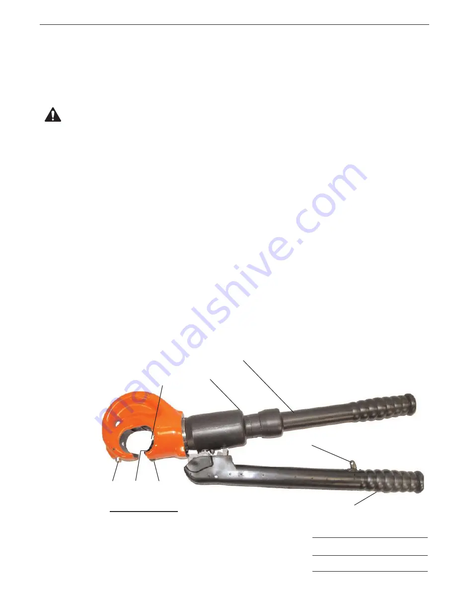
1. Top Die Release Button
2. Bottom Die Release Button
3. Piston Guide Screw
4. Piston

5. Reservoir
6. Reservoir Handle
7. Release Striker
8. Pump Lever

Illustration

Summary of Contents for POWER TEAM C12-TON

Page 1: ...y pulling the trigger on the pump lever and making another pumping stroke It will retract only to the positions previously set thus minimizing the amount of pumping needed to complete the next compression Note that all operating controls are located such that the operator need not remove his hands from the tool THE C12 TON TOOL IS NOT TO BE USED FOR HOT LINE WORK SPECIFICATIONS PUMP SECTION SINGLE...

Page 2: ...jury and or infection Exercise caution to avoid the risk of fire An incomplete crimp can cause a fire Use proper die connector and cable Improper combinations can result in an incomplete crimp This tool is not insulated When using this unit near energized electrical lines use proper personal protective equipment This tool is intended for two handed operation Maintain a firm grip on both handles du...

Page 3: ...the valve will cause an audible click and a pronounced difference in the feel of the pumping To retract the ram open the compressor handles hold the pressure release trigger down and close the handles firmly to push in the pressure release plunger The ram will retract to the pre selected position If the die opening must be increased further use same procedure as above and while the trigger is held...

Page 4: ... Service should be performed by adequately trained personnel in repair shops under clean conditions For those owners having adequately staffed repair facilities a hydraulic seal replacement kit No 3 3554 containing O rings gaskets etc needed for one complete replacement of hydraulic seals in the compressor Include compressor serial number when ordering all parts To replace the seals it is necessar...

Page 5: ... full the ram is likely being held by a deformed washer A small amount of leakage is desirable around the ram pump plunger and pressure release valve plunger to lubricate these parts If enough leakage occurs to cause the oil to run the packing should be replaced If rotating the reservoir handle will not advance the ram to within a half inch of closing the dies additional oil is needed in the compr...

Page 6: ...Rubber Covering Cap 18 3 1197 1 Piston Reservoir 19 3 5071 1 Rubber Covering Cylinder 20 3 1201 1 Cap Reservoir 21 5 1260 1 Quad Ring 1 5 8 x 1 7 8 x 1 8 22 3 1195 1 Cylinder Assembly 23 5 1263 1 O Ring 24 5 1259 2 Screw 10 24 x 1 4 SHCS 25 12356 2 Washer Tooth Int 37 x 20 26 3 1214 1 Ring Back up 27 3 1193 1 Ram Assembly 28 3000094 1 C Head Assembly Coated ITEM NOT SHOWN 2000147 1 Bag Nylon Carry...

Page 7: ... 5 4 A A B B C C 1 3 1246 1 Lever 2 3 1248 1 Striker Release 3 3 1249 1 Shaft 4 3 1250 2 Bushing Lever 5 3 1251 1 Pin Plugger 6 3 1252 1 Spring Striker 7 3 1253 1 Trigger 8 3 1254 1 Covering Rubber Lever 9 5 1265 1 Pin 10 5 1269 1 Pin 11 5 1270 1 Pin 12 5 1271 1 Pin Item Part No Item Part No No No Req d Description No No Req d Description LEVER ASSEMBLY 3 1192 ...

Page 8: ...rimped 3 5 0662 1 Screw Set 4 3 1239 1 Spring 5 5 1265 1 Pin Driv lok 6 3 1238 1 Pin Die Retaining Item Part No Item Part No No No Req d Description No No Req d Description Operating Instructions and Parts List Form No 1000026 Back sheet 4 of 6 PARTS LIST C HEAD ASSEMBLY 3000094 ...

Page 9: ...r Screen 6 3 1219 1 Plunger Pump 7 3 1220 1 Spacer Packing 8 3 1221 1 Ring Packing 9 3 1222 1 Plunger Release 10 3 1223 1 Nut Plunger 11 3 1225 1 Screen Intake 12 3 1226 1 Spring Compression 13 3 1227 1 Washer Nylon 14 3 1228 2 Washer 15 3 1229 1 Spring Compression 16 3 2716 1 Valve Assembly HP Relief 17 10377 1 Ball 18 10423 1 Ball 19 14763 1 O Ring 20 10375 1 Ball 21 10268 1 O Ring 22 10374 1 Ba...

Page 10: ...N A A B B A A SECTION B B 3 4 1 10 Operating Instructions and Parts List Form No 1000026 Back sheet 5 of 6 PARTS LIST H P RELIEF VALVE ASSEMBLY 3 2716 RAM ASSEMBLY 3 1193 1 3 1239 1 Spring 2 3 1240 1 Rod Spring 3 3 1241 1 Pin Retaining 4 3 1242 1 Shaft Release 5 3 1243 1 Ram 6 3 1244 1 Spring 7 3 1245 1 Support Spring 8 5 1266 1 Ring Retaining 9 5 1267 1 Pin Roll 10 5 1269 1 Pin Roll Item Part No ...

Page 11: ... Item Part No Item Part No No No Req d Description No No Req d Description 1 3 2 A A A A 1 2 Note Use 5 2840 Adhesive to fasten spacer in place Spacer must not project above O D Parts must be clean dry and free of grease and oil prior to applying adhesive Operating Instructions and Parts List Form No 1000026 PARTS LIST Sheet No 6 of 6 Rev Date 09 Feb 2004 RESERVOIR HANDLE ASSEMBLY 3 1196 RESERVOIR...

Reviews: