


8
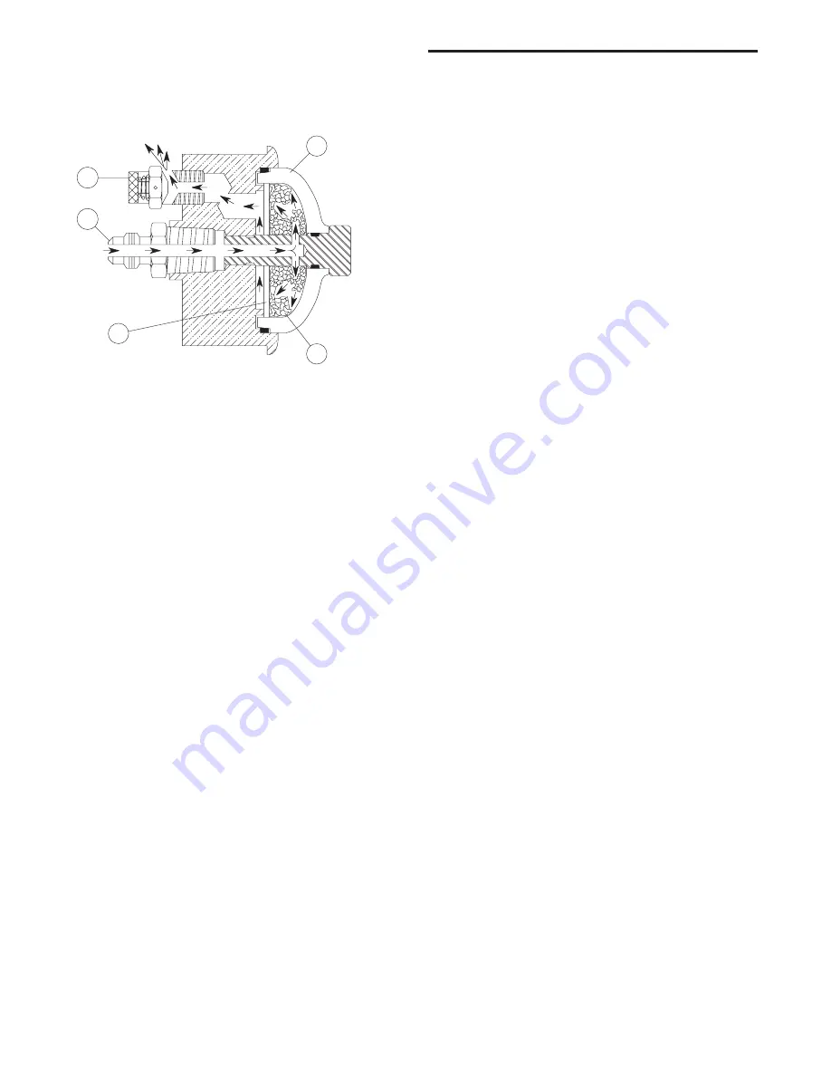
from blue (dry) to pink (wet), alerts personnel of a dryer-
associated moisture problem which requires investiga-
tion. The gas exits the indicator through a porous disc
(4) and then vents to atmosphere through an adjustable
bleed valve (5).
Figure 2
Color Change Moisture Indicator
5.4 Valve Switch-Failure Alarm (Option)
Limit switches are located on each switching valve to
trigger an alarm when any valve is not in the correct posi-
tion. If triggered, the dryer control system will energize
the red alarm LED on the control panel and de-energize
the common alarm relay. The alarm automatically clears
once the alarm conditions are corrected.
5.5 Dew Point Control (Option)
This option monitors and displays outlet pressure dew
points and provides an alarm signal if the dew point
exceeds user-specified set point. Recommended cali-
bration interval is 12 months. Contact the service depart-
ment for details.
Operation – The dew point is measured at the dryer oper-
ating pressure and is displayed in the operator interface.
When the controller is configured for Dew Point Control
mode, the on-stream tower will not switch and regenerate
until a predetermined dew point has been reached. This
elimination of unnecessary heat cycles extends dryer
desiccant and component life.
To protect the dew point transmitter from high tempera-
tures and dew point, a solenoid valve is used to isolate
the transmitter immediately after tower reversal.
If the dew point transmitter fails or reports a reading
outside of its operating range, the display will indicate a
sensor failure alarm condition. If the dryer is configured
for Dew Point Control mode when a transmitter alarm
occurs the controller will revert to the Standard Cycle until
the alarm condition clears.
6.0 Operation
6.1 Controls
A solid-state controller monitors all critical operating con-
ditions, and indicates operating status on a 2-line LCD
display operator interface. The controller receives input
data from temperature sensors, limit switches (option),
the Dew Point Transmitter (option) and the operator
interface. The operator interface displays information
about the dryer operating status and is used to change
the dryer operating mode.
6.2 Operating Modes
6.2.1 Automatic and Manual Advance
The drying and regeneration cycles are divided into
discrete steps. The operator selects either one of the
automatic modes (Fixed Cycle, Standard Cycle or Dew
Point Control) or manual advance mode (Manual Mode)
through the operator interface.
Selecting any of the automatic modes enables the
controller to advance the program step-by-step according
to the programmed schedule.
Setting up the controller for manual advance allows the
operator to advance the program one step at a time. This
mode is used for diagnostic purposes.
6.2.2 Fixed Cycle, Standard Cycle and Dew
Point Control
Fixed Cycle:
Each tower is on-line (drying) for a set
minimum time period.
Standard Cycle:
Each tower is on-line (drying) for a set
minimum time period plus any additional time required to
complete bed heating during low flow conditions. At lower
than design flow rates, the time required for bed heat-
ing will increase which will result in a longer drying time
between regenerations and fewer desiccant heat cycles.
Dew Point Control:
Each tower remains on-line (dry-
ing) until the desiccant bed has been fully utilized. For
lower than designed moisture loads, this results in longer
drying cycles, longer time between regenerations and
fewer desiccant heat cycles. Dew Point Control is an
optional feature.
The operator interface is used to select the operating
mode.