12
9.
Service Instructions
9.4
Installation of the valve
MF4, MEF4
a. CU design:
Fix the adapter at the actuator.
Place the control unit
(20)
on the adapter
(22)
and secure it
with the ring.
Valve position indicator:
Fasten the indicator housing
(18)
.
b. To assemble the valve insert in the NC design, proceed
as follows:
Place the valve insert carefully in the valve housing.
The o-ring
(4)
must not be damaged during the installation in
the housing.
Actuator in NC design:
control actuator with min. 6 bar
pneumatic air.
Screw the hex. screws
(11)
in the housing flange and tighten
them crosswise.
Do not touch movable parts!
Risk of injury.
!
NC design:
cut off air.
c. Check the basic adjustment of the valve position indicator.
-
By turning the positioning screws in the control unit, the shift
points can be adjusted.
d. Design with valve position indicator:
Plug in and fasten the proximity switches.
-
Readjust the proximity switches if necessary.
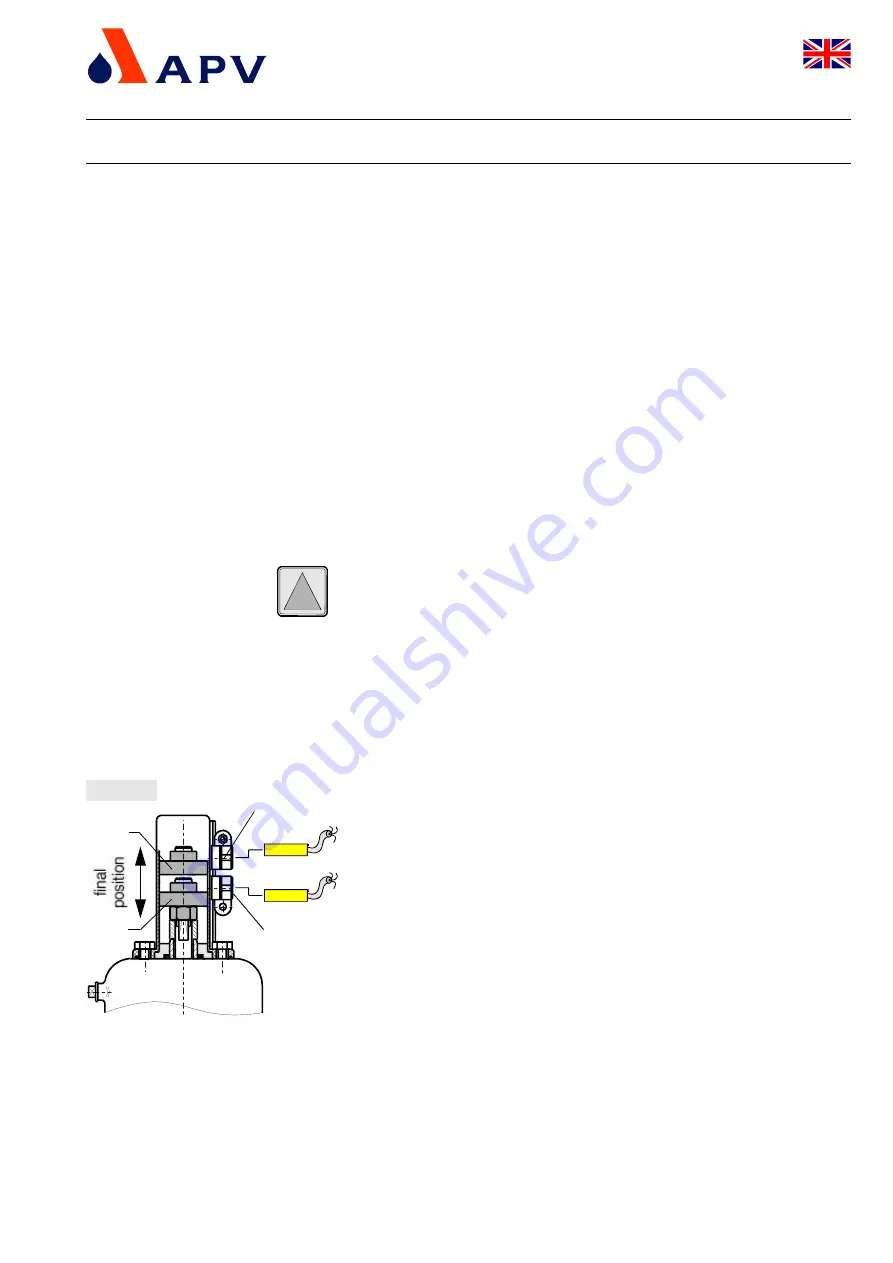
e. Adjustment of proximity switches: (fig. 9.4)
-
Move the actuator into one final position.
-
Move the corresponding proximity switch into the corresponding
position. For this purpose, release the positioning screw and move
the holder until the corresponding signal is indicated. Then,
continue to slide by 2 to 3 mm to secure the indication.
Tighten the positioning screw.
-
Place the actuator in the other final position and position the
second proximity switch.
-
Upper valve position indication:
valve "normally open"
NO
-
Lower valve position indication:
valve "normally closed"
NC
!
positioning screw
proximity switch
holder
NC
NO
fig. 9.4
UK
DELTA MF4-UK0.qxd / 12.2004
Membrane Valve with Bellow Unit
DELTA MF4
Operating Manual rev. 0


