5
020-047 R2 EN
BoomPilot
®
Figure 4: LED description
Section power
On – boom section power is on
Off – boom section power is off
In/out error
Off – boom output is high or on
Blinking – boom output is low or off
Auto mode
On – auto mode is active
Off – manual mode is active
CAN data
Blinking – receiving console CAN messages
Off – CAN messages stop for > 3 seconds
CAN power
On – CAN power is on
Off – CAN power is off
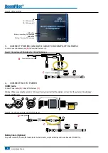
3. DiSconnect & reconnect harneSSeS & cabLeS
The BoomPilot SDM harness
(C)
tees into the existing system’s connection between the Blanchard REB3 rate controller and the switchbox.
1. Disconnect existing connection between the Blanchard REB3 rate controller and the switchbox.
2. Connect BoomPilot harness
(C)
to the switchbox.
3. Connect BoomPilot harness
(C)
to Optima Module Interface.
4. Connect Optima Module Interface to existing Blanchard REB3 console.
Figure 5: Switchbox to BoomPilot harness to Optima Module Interface
B
A
A
B
xxx-xxx
xxyyxx
Connect C to switchbox
B
A
A
B
xxx-xxx
xxyyxx
Connect C to
optima module interface
Connect optima module interface
to Blanchard console
Summary of Contents for TeeJet BOOMPILOT
Page 11: ...9 020 047 R2 EN BoomPilot...


