background image

DLS 6700 Operating Manual

Spirent Communications 

7104000557

Page 7-1

7.

CUSTOMER SUPPORT

7.1 Customer Service Contact Information

For all North American customers, please direct any questions or concerns regarding 

the operation of a purchased unit, to the Spirent Communications Customer Service 

team by one of the following methods:

Direct Line:  613-592-7301
Toll free at:

800-465-1796

Fax at: 

613-592-0522

E-mail at: [email protected].

All other customers should check the ae.spirentcom.com web site for the contact 

information of the nearest Customer Service center or contact the main Spirent Com-

munications service center for assistance (contact information is listed above).

For product information and updates, please visit the Spirent Communications web 

site at:

https://ae.spirentcom.com

For product manuals, software updates and more information, please visit the cus-

tomer extranet at:

http://ae.spirentcom.com/secure/

Passwords for the extranet can be requested at:

http://ae.spirentcom.com/Customer_care/needlogin.htm

7.2 Protecting Your Investment

Spirent Communications is committed to providing the highest quality products and 

customer support possible. An annual calibration is required to ensure that your unit 

is operating properly.
Spirent Communications is pleased to offer two cost effective optional service pro-

grams. Each of these programs is designed to improve the ease and efficiency of 

servicing Spirent Communications test equipment.

7.3 Extended Warranty

Spirent Communications' Extended Warranty gives two years in addition to the 
original one-year manufacturer’s warranty. Under the warranty agreement, Spirent 
Communications repairs any covered product that needs service during the warranty 
period. At the time of repair, any required firm ware and/or software upgrades are 
installed free of charge and if required as part of the repair, the unit receives a 
complete calibration. Spirent Communications also provides return shipment of any 
unit covered under warranty at Spirent Communications’s cost.

The Extended Warranty gives:

Summary of Contents for DLS 6700

Page 1: ...P N 7104000557 User Guide DLS 6700 Operating Manual Version 1 02 Nov 2004...

Page 2: ...anada K2V 1C7 Support Contacts Canada E mail ae service spirentcom com Web http ae spirentcom com Toll Free 1 800 465 1796 Phone 1 613 592 7301 Fax 1 613 592 0522 Europe E mail support europe spirentc...

Page 3: ...6700 Software 3 1 3 1 1 Installation 3 1 3 1 2 Starting the DLS 6700 Software 3 1 3 2 Communications Interface Selection 3 2 3 2 1 Identify Chassis 3 2 3 2 2 Start Online 3 2 3 2 3 Start Offline 3 2 3...

Page 4: ...ents 10 2 11 SAFETY 11 1 11 1 Information 11 1 11 1 1 Protective Isolation 11 1 11 1 2 Before Operating the Unit 11 1 11 1 3 Power Supply Requirements 11 1 11 1 4 Fuse Configuration 11 1 11 1 5 Connec...

Page 5: ...ireline Simulator The DLS 6700 ADSL2 Wireline Simulator simulates 26 AWG cable for ADSL2 ADSL2 ADSL2 ADSL production and verification testing It has a reach of up to 24 kft in 1 000 ft increments and...

Page 6: ...nfiguration software that ships with the DLS 6700 provides you with full control over the characteristics of each DLS 6700 simulated loop We recommend that you develop your own scripts based on the ty...

Page 7: ...cess multiplexer DSLAM equipment to one of the Output ports at the back of the DLS 6700 4 Connect customer premise equipment CPE equipment to the corresponding Input port at the back of the DLS 6700 5...

Page 8: ...nel 2 4 1 Reading Remote and Power Status The POWER LED turns green when the power is turned on The power LED blinks red if it fails its self test or solid red if it detects an internal error The REMO...

Page 9: ...n AC power supply appropriate for your specific country Please see Chap ter 10 SPECIFICATIONS for more details The power LED will turn on when the power is connected WARNING Before operating the unit...

Page 10: ...software You can use the included Spirent Communications s GUI to configure the DLS 6700 or you can develop your own custom configuration software using the DLS 6700 com mand set This command set is c...

Page 11: ...compatible computer 3 1 1 Installation To install the software run SETUP EXE from the installation CD if it does not start au tomatically when the CD is inserted The user is prompted to specify the d...

Page 12: ...tion button will appear and all the other buttons will be disabled until the Stop Iden tification button is clicked 3 2 2 Start Online Once the correct COM Port is selected click Start Online to use...

Page 13: ...ping feature is a convenient way to set many lines at once Select the lines to be modified and then apply a length to the grouped lines Figure 3 2 DLS 6700 Main Editing Grid To specify which lines are...

Page 14: ...nes is pressed whereas the individual line length is applied as soon as the value is changed 3 4 Menu Selections 3 4 1 File Load Retrieves a previously stored file of DLS 6700 settings from disk Save...

Page 15: ...OT use a null modem with a computer that has a standard COM port configured as a DTE The DLS 6700 stops transmitting data when the RTS line is low and restarts when the RTS line is high The DLS 6700 l...

Page 16: ...mit ESR check if an error occurred 5 read the answer If not 0 an error has occurred See Event Status Register ESR Section for description of the error s 4 2 Data Formats The DLS 6700 adheres to the IE...

Page 17: ...character ASCII LF decimal 10 hex 0A Messages from the 6700 are always terminated with a Line Feed character As defined in the SCPI specifications a Device Dependent Command may be sent in its short...

Page 18: ...adjusted to between 1 kft and 24 000 kft in 1 000 ft increments For example to set the length of line 1 to 4 000 ft send SET CHAN LINE 1 4000 ft To set the length of all the lines to 4 000 ft send SE...

Page 19: ...mmand will return the pacing method as a string For example if the pacing method is RTS CTS the returned message will be RTS CTS To simplify the setting of the serial interface we used a slightly modi...

Page 20: ...lue between 0 and 255 representing the value of the Event Status Enable Register ESER is placed in the output queue The possible values are described in the ESE command section and in more detail in S...

Page 21: ...ar the Service Request Enable Register and the Standard Event Status Register at power on If 1 or higher then all the enable registers are cleared at power on if 0 then all the enable registers are re...

Page 22: ...the output queue The possible values are listed in the SRE command section STB Status Byte Query Type Status command Function The value of the Status Byte Register is put into the output queue Con tr...

Page 23: ...record and report the system status the Status Byte Register STB and the Event Status Register ESR For both registers there are three basic commands one to read the register one to set the enabling b...

Page 24: ...t to read an empty output queue or there was an output queue overflow maximum output queue capacity is 75 bytes bit 3 Device Dependent Error This error bit is set when the DLS 6700 receives a command...

Page 25: ...leted Make sure that all the required enable bits are set When using OPC or OPC the program controlling the DLS 6700 can determine when the operation is completed by waiting for SRQ or by reading the...

Page 26: ...DLS 6700 Operating Manual Page 4 12 7104000557 Spirent Communications...

Page 27: ...ects an internal error it does a full system initialisation and turns the power LED orange If this happens consult the factory 3 The remote LED is off This is normal after both a power up and a reset...

Page 28: ...DLS 6700 Operating Manual Page 5 2 7104000557 Spirent Communications...

Page 29: ...nication Union Place des Nations CH1211 Geneva 20 Switzerland ITU T Draft Recommendation G 992 5 ADSL2plus specification International Tel ecommunication Union Place des Nations CH1211 Geneva 20 Switz...

Page 30: ...DLS 6700 Operating Manual Page 6 2 7104000557 Spirent Communications...

Page 31: ...sswords for the extranet can be requested at http ae spirentcom com Customer_care needlogin htm 7 2 Protecting Your Investment Spirent Communications is committed to providing the highest quality prod...

Page 32: ...ormance Specific Spirent Communications products are shipped with a National Institute of Standards and Technology N I S T traceable calibration that expires one year from the original ship date With...

Page 33: ...overed under this warranty the reg ular repair charges shall apply to any repairs made to the equipment For international customers please contact your local Spirent Communications sales representativ...

Page 34: ...DLS 6700 Operating Manual Page 8 2 7104000557 Spirent Communications...

Page 35: ...e unit It is highly recommended that all shipments are marked with labels indi cating that the contents are fragile If sending a unit back to the factory ensure that the Return Material Authorization...

Page 36: ...DLS 6700 Operating Manual Page 9 2 7104000557 Spirent Communications...
Page 37: ...ft increments Bandwidth DC to 4 5 MHz DC Rating 100 V Attenuation Insertion Loss MAE 1 dB 20 kHz 4 5 MHz Typically simulation vs theory Impedance 10 20 kHz 4 5 MHz Control Remote via RS 232 port Conn...

Page 38: ...g Manual Page 10 2 7104000557 Spirent Communications 10 4 Carton Contents 1 DLS 6700 ADSL2 Wireline Simulator 2 AC to DC Wall Plug in Adapter 3 RS 232C Cable 4 Control Software for Windows 98 NT 2000...

Page 39: ...12 V Note that the polarity of the DC Plug is The inner conductor is positive and the outer conductor is negative See symbols in the Safety section The maximum current taken is 400 mA 11 1 4 Fuse Conf...

Page 40: ...ing the Unit Inspect the equipment for any signs of damage and read the Operating Manual thoroughly Install the equipment as specified in the relevant section of this manual Ensure that the equipment...

Page 41: ...Communications 7104000557 Page 11 3 When any of these symbols appear on the unit this is their meaning EQUIPOTENTIALITY FUNCTIONAL EARTH TERMINAL PROTECTIVE GROUNDING CONDUCTOR TERMINAL CAUTION REFER...

Page 42: ...DLS 6700 Operating Manual Page 11 4 7104000557 Spirent Communications...
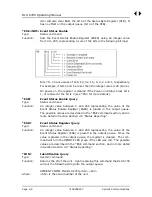
Page 43: ...st be 100 for 24AWG or 26AWG North Hills 0301BB or 135 Ohm for TP100 North Hills 0312BB in order to match the reference impedance indicated in the standards The center tap on the balanced side is usua...

Page 44: ...ts and outputs separate The use of a high impedance measuring device with no load from tip to ring at the receive end This results in reflections due to a bad mismatch at the end of the line and leads...

Page 45: ...kft Figure A3 3 DLS 6700 Attenuation at 16 kft 18 kft 20 kft and 24 kft Attenuation Characteristics 80 70 60 50 40 30 20 10 0 0 1 0 2 0 Frequency MHz Attenuation Theory Measured 8 kft 10 kft 12 kft 1...

Page 46: ...DLS 6700 Operating Manual Page A 4 7104000557 Spirent Communications...

Page 47: ...below F i g u r e 1 7 H P 4 3 9 Figure B 1 HP 4395A Noise Floor Figure B 1 demonstrates the Agilent 4395A spectrum network analyzer s Noise Floor over a Bandwidth of 0 30MHz The graph shows that for f...

Page 48: ...DLS 6700 Operating Manual Page B 2 7104000557 Spirent Communications...
Reviews: