


Note:
If the controller is configured as an
ON/OFF controller the whole group 2
parameters will be occulted and
replaced by:
Hysteresis
0.1 to 10.0% span
0:5
Baude Rate
9600 *
1
4800
2
2400
3
1200
600
0
4
Parity
None
1
Odd
2
Even
3
None*
None*
0
4
User
User
User
Modbus
Jbus
Protoc.
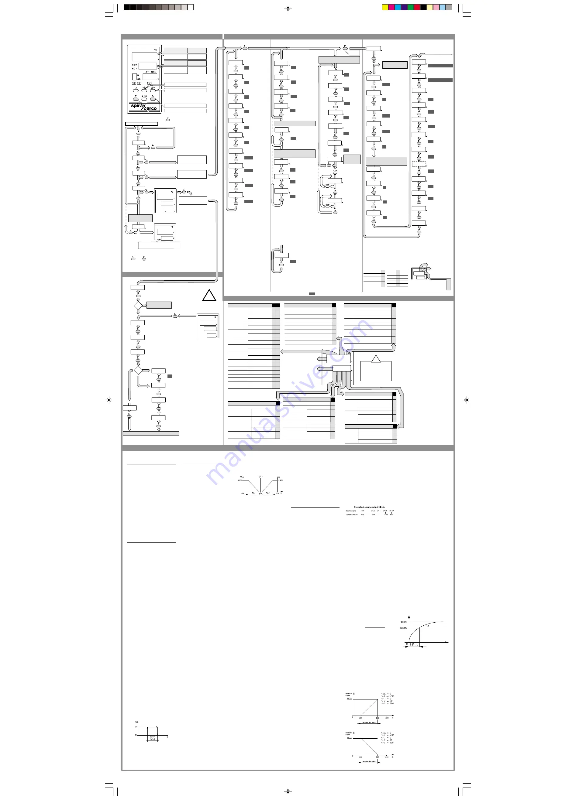
GROUP 1 - SETPOINTS
CONFIGURATION CODE
6•PROGRAMMING INSTRUCTIONS • SX75 SERIES CONTROLLERS
GROUP 3 - ADVANCED FUNCTIONS
PARAMETERS
FUNCTIONS MENU
Loop - Break - Alarm
0.…10 Vdc
9
Type of control action and safety position Y1(3)
0
1
2
3
4
*
5
Reverse
Safety
0%
Direct
0%
100%
100%
-100%
-100%
H
*
(Yh)
(Yh)
(Yh2)
(Yh2)
Reverse
Reverse
Reverse
Direct
Direct
Direct
Direct
Safety
Safety
Safety
Safety
Safety
Safety
Safety
Safety
Safety
Conf
Off
Off
Conf
(4)
(4)
6
7
8
0 to 200 sec
CONFIGURATION
if not configured at
the power-up the
main diplay will
show:
!
Entering the configuration
process
Follow
0 to 200 sec
Event Y2 type
0
1
2
3
4
5
6
7
8
I
Disabled
Deviation with
startup inhibition
Active high
Active low
Band
Active outside
Active inside
Process
Active high
Active low
Deviation
Active high
Active low
Type of control output Y1 (2)
Relay with time-proportioning
1
Logic 0/24 Vdc with time-proportioning
2
4…20 mAdc
3
0…10 Vdc
4
*
6
*
7
4…20 mAdc
*
8
9
G
5
Valve motor drive
Logic 0/24 Vdc with time-proportioning
Relay with time-proportioning
Reverse
9
0
1
2
3
Type of Set point
N
Standard
1 Local
1 Local and Remote 4…20 mA
1 Local and Remote 0…10 Vdc
1 Local + 4 stored
Retransmission output Y4
0
1
2
3
4
5
6
M
None (5)
4…20 mA
Retransmission measurement X
Retransmission Set point W
Retransmission Y1
0…10Vdc
(6)
Retransmission measurement X
Retransmission Set point W
Retransmission Y1 Cool
Event Y3 type
0
1
2
3
4
5
6
7
8
L
9
Disabled
Deviation with
startup inhibitor
Active high
Active low
Band
Active outside
Active inside
Process
Deviation
Active high
Active high
Active low
Active low
1
st
group
2
nd
group
Parameter
protection code
Visible and modification
Visible but NO MODIFICATION
NOT VISIBLE
Security Access
2
1
0
*
0
Relay (On - Off with hysteresis
PARAMETERS DESCRIPTION
Serial
communications
SX75+ only
User
GROUP 2 - CONTROL FUNCTIONS
Press F for
group 3
Press F for normal
operation
To scroll through the menu, press
Normal Operation
Y
Run Auto - Tune
function
Modify or view
Parameters
Start Configuration
Procedure
View
Set point
View
Configuration code
View instrument
Device number 0 … 63
First block of 4
configuration code
E,F,G,H
Second block of 4
configuration code
I,L,M,N
You can configure your
instrument by entering the 8
characters code
*
Only for Heat-Cool applications
Enter correct
Password
1111
From configuration
process
Error: return to
normal operation
Set point
limit low
Beginning of the scale
Set point
limit high
End of the scale
Maximum power
output (heat)
10 to 100%
100
100
Maximum power
output (cool)
10 to 100%
0022
Security access for
parameters (see note)
0000 to 0022
Autotune function
0
Disabled
1
Enabled
0
For serial communication
SX75+ model only
3 Allowable event alarm set points
depend upon the type of alarm
configuration
• Deviation alarm : -300 to +300
• Band alarm:
0 to 300
• Independent:
on full scale
4 Parameters Y2 and Y3 event
a l a r m s w i l l n o t a p p e a r i f
configuration code
I=0 (Y2) and L=0 (Y3)
Note:
factory set parameters
DISPLAY
Measured Value
Set point
Function
mnemonic
during normal
operation
KEYS
Digit select
Increment value
Enter
Function
Function value
during
programming
Input type, scale range (1)
-200…600
°
C
0
0
-200…600
°
C
0
2
-99.9...300,0
°
C
1
0
Conf -99,9...300.0
°
C
1
2
0...600
°
C
2
0
within 0...600
°
C
2
2
0...600
°
C
3
0
0...600
°
C
3
2
0...1200
°
C
4
0
0...1200
°
C
4
2
0...1600
°
C
5
0
0...1600
°
C
5
2
0...1600
°
C
6
0
0...1600
°
C
6
2
eng. units
7
4
eng. units
7
5
eng. units
7
6
eng. units
7
7
E F
RTD
Pt100
IEC 751
Thermocouple J
Fe Cu 45%Ni
IEC 584
Thermocouple L
Fe-Const
DIN 43710
Thermocouple K
Cromel-Alumel
IEC 584
Thermocouple S
Pt10%RhPt
IEC 584
Thermocouple R
Pt13%RhPt
IEC 584
4...20 mA
0...20 mA
0...1 Vdc
0...10 Vdc
Conf.
Conf.
Conf.
Conf.
Conf.
Conf.
Conf.
Conf.
Conf.
Conf.
Yes
Time constant of
the input filter
0 to 30 secs
Input shift
-50 to 50 digit
0
0
1
st
Set point
10
2
nd
Set point
3
rd
Set point
(See Note 1)
4
th
Set point
(See Note 1)
Slope up between the
Set point 0.0 to 100.0
step/min.
(see note 2)
20
30
40
Slope down during
transition of the Set point
0.0 to 100.0 step/min.
(see note 2)
Y2 Event alarm set
point (see note 3)
300
Y3 Event alarm set
point (see note 3)
300
Y
2
Hysteresis
to 10.00% span
0:50
Y
3
Hysteresis
0.01 to 10.00% span
0:50
0:0
0:0
Note:
1 Set points will only be shown
if configuration
code N=3
2 If slope gradient = 0
there will be a step change
between set points
30
Cycling time Y2
(only for heat/cool time
proportional output.)
Only for Heat/Cool controller
(configuration G = 6 to 9)
for serial comms
SX75+ only
Serial Communication status
enabled to write
If
or
is not pressed within 10 seconds the instrument
will time-out back to the process variable.
Note:
1
Enter correct password to start
configuration process (
3333
)
Return to normal
operation
Enter the first block of 4 configuration
codes -E, F, G, H
Number of decimal places EF (Applies
to configuration codes 74 to 87 only)
Configurable input
scale low value
YES
Enter the second block of 4 configuration
codes I, L, M, N
Configurable input
scale high value
For time proportional output
1:0
Dead band
0.0 to 5.0% output
Only for valve motor drive
output (configuration G = 5)
Minimum power
output (heat)
0 to 100%
0
during normal
operation
during
programming
QWtune
2
3
4
u
d
Y1 Safety
( H = 6 or 7)
30
Cycling time Y1
(only for time proportional
output.)
Calibrate
maximum
position of valve
Accept
calibration point
Accept
calibration point
Calibrate
minimum
position of valve
Calibrate
potentiometer
feedback
The valve is driven
to minimum
position
Valve
movement
sensitivity
0.1 to 10%
Time for full
valve travel
15 to 600 sec.
Y2 Event safety
action
0
= disab
led
1
=
closed
contact
2
= open contact
Remote set point
0
= Remote
1
=
Remote
+ local
Remote Ratio
—100 to 100
Remote Bias
sc.Io
…
sc.hi
if at the power-up
you see
9999
-
9999
that means the instrument
IS NOT CONFIGURED
!
2
1
Fuzzy scale
amplitude
0.5 to 999.9%
Fuzzy scale on
change on error
0.10 to 99.99%
Time Sampling
0 to 30 sec.
(0 = 0.5 sec.)
Device Number
0…63
0
Parity
0 to 4 (see note 3)
1
Baud rate
0 to 4 (see note 2)
Serial
Communications
status
0
= OFF;
1
= ON
Proportional band
0.5 to 999.9%
5:0
Integral time
0.0 to 100.0 minutes
1:0
Derivative time
0.00 to 10.00 minutes
0:20
Fuzzy intensitity
0.0 to 90.0%
50
Proportional
band
0.5 to 999.9%
5:0
Integral time
0.0 to 100.0 min.
5:0
Derivative time
0.0 to 10.00 min.
1:00
Fuzzy intensity
0.0 to 90.0%
50
NOTES:
5 For Pt100 and thermocouple inputs with
configurable scale, it advised to select
the largest range possible. The minimum
span should be no less than 25% of the
maximum range. Note: within the selected
range, it is possible to limit the set point low
and high limit settings (Spl l and Spl h).
For mA and Volts inputs, low and high scale
values can be configured in engineering units
between -999 and 9999. The minimum scale
span is 100 steps. The v alues can be
expressed in units (xxxx), in tenth (xxx.x),
hundredths (xx.xx), or thousandths x.xxx).
6 A switch located inside the controller
provides selection of analogue outputs.
See paragraph 4.6 of the IMI
7 The safety state is the value assumed by
Y1 in event of input signal failure it is the
value defining the upper limit of Y1. Safety
states with * (H-4) or (H-5) impose the
maximum limit to Cool action.
8 Selecting H(6,7) it is possible to set
the safety value assumed by parameter say
1 in event of an input signal failure.
9 Configuration code M applies to SX75+
models only.
10 To change from 4...20 mA to 0...10V
alter the jumper switch position.
1:0
Cool relative gain
0.1 to 3.0
60
1:0
20:0
10:00
3
Y3 Event safety
action
0
= disab
led
1
=
closed contact
2
= open contact
sc.Io
10
0
0
Advance to group 3 parameters
OK
1
ERROR
°
C -
°
F selection
(Applies to EF configuration codes 00 to 62 only)
0 =
°
C
1 =
°
F
Y1 Safety
( H = 6 ou 7)
Exiting the configuration process you will access group 3
parameters to modify, if necessary, Set point limits,
maximum power output etc…
F = 0
EF =74…87
F =2
8
4
8
5
8
6
8
7
4...20 mA
0...20 mA
0...1 Vdc
0...10 Vdc
Conf. eng. units with
√
Conf. eng. units with
√
Conf. eng. units with
√
Conf. eng. units with
√
*
Only for Heat-Cool applications
275.8
275.8
4
50
s.p. t
tune
par.
C o n f
Addr
4230
7500
Co
63
Addr
s.p. 2
s.p. 3
s.p. 4
s.p. 1
s1. u
s1. d
y25.p
y HYYy
y35.p
y3Hy
p.b.
t.i.
t.d.
f.1nt.
t.c.
t.c. 2
d.b.
rcr
p.b.
t.i.
t.d.
f.1nt.
t.y.
dy.
pot.1
pot.1
pot.h
pAss
A.par
A.tu.
A.tu.
f.Err
f.der
t.san
s.C.1
Addr
s.C.b.r
s.p.r.1
s...p.l.1
s.p.r.2
s.p.r.3
yl.
yh.
yh. 2
t.fil
1n.5h
sa.y2
sa.y3
s.C.pa
0022
A.par
2
pAss
Con.1
Con.2
C-f
sa.y1
sa.y1
sc.hi
sc.1o
sc.dd
4230
9999
9999
Co
Hy
.
operation
7500
Co
0.01
Entering parameters
When configuration phase is com-
pleted, the controller can display all
the parameters of functions that may
be entered to their desired values. To
simplify the exercise the parameters
have been divided into three groups .
Group 1 covers the parameters re-
lated to the set point. Group 2 covers
control parameters. The third group,
which is protected by the password
1111, are the advanced parameters.
These include the security access,
the fuzzy control parameters, the pa-
rameters for the serial com-
munication, all the limiting functions
and safety states functions.
First group of parameters
s.p.
.1
Stored set point 1 (N = 3)
s.p.
.2
Stored set point 2 (N = 3)
s.p.
.3
Stored set point 3 (N = 3)
s.p.
.4
Stored set point 4 (N = 3)
The memorised set points are the pre-
set values for operation, recalled
through logic inputs, serial transfer or
the front keyboard. When one of these
set values is recalled the small auxil-
iary display on the front of the instru-
ment shows the set number recalled.
sl. u.
Rate of change for increase
of the main set point SP.
Any new value of the main set
point SP greater than that pre-
viously entered set point will
change at the rate entered into
this parameter. The slope is
expressed in digits/minute.
sl. d.
Rate of change for decrease
of the main set point SP.
Any new value of the main set
point SP less than that previ-
ously entered set point will
change at the rate entered into
this parameter The slope is
expressed in digits/minute.
y
Y2sp
Set point of event output Y2
(I = 1 to 8)
y
2Hy
Hysterisis of event output Y2
(I = 1 to 8)
Hysterisis is a zone within which
an output does not change and
maintains the state previously
assumed. In order to obtain a
change in the state of the meas-
ured value X it is necessary to
go outside this zone. The am-
plitude of this hysterisis zone is
expressed as an amplitude %
of the configured scale.
y3sp
Set point of output event Y3
(L = 1 to 8) See
y2sp
y3Hy
Hysterisis of output event Y3
(L = 1 to 8) See
y2hy
Second group of parameters
Hy
Hysterisis of relay output Y1
(G = 0)
The hysterisis is a zone within
which an output does not
change and maintains the state
previously assumed. In order
to obtain a change in the state
of variable X it is necessary to
go outside this zone. The am-
plitude of this hysterisis zone is
expressed as an amplitude %
of the configured scale. The
output contacts are to be found
between terminals 16 and 17.
p.b.
Proportional band (G = 1 to 9)
The band within which the
modulation of the output in di-
rect proportion to the difference
between the set point W and
the measured value. It is calcu-
lated as a % of the input span.
t.i.
Integral time (G = 1 to 9)
This is the time used by a single
integral action to repeat the pro-
portional action. This action is
expressed in minutes.
t.d.
Derivative time (G = 1 to 9)
This is the time taken for a
single proportional action to
attain the same level as the P
+ D output. This action is
expressed in minutes.
f.int
Percentage intensity of fuzzy
action (G = 1 to 9).
The main control output is com-
posed of the sum of two control
algorithms, Fuzzy and PID. This
parameter permits the balanc-
ing as a % of the proportion of the
fuzzy algorithm in relation to that
of the PID. With most applica-
tions the default value of 50%
would be suitable.
tc
Cycle time of the output Y1
(G = 1,2,6,7)
This parameter is expressed in
seconds and defines the total
time of the On/Off states of the
main output Y1 modulated in %
of the PID + Fuzzy algorithm.
e.g. If Y1 = 20% and t.c. = 30”,
the On state = 6” and that of the
Off = 24”.
If G = 1 or 6, the output relay
contacts are between terminals
16 and 17.
If G = 2 or 7, the logic output as
a voltage is available between
the terminals 19(+) and 20(-).
tc 2
Cycle time for “cooling out-
put” Y1
(G = 6 to 9 and M = <> 3, <> 6).
This parameter is expressed in
seconds and defines the total
time of the On/Off states of the
cold output Y1 modulated in %
of algorithm PID + Fuzzy.
e.g. If Y = -20% and tc2 = 30”,
the On state = 6” and that of the
Off = 24”.
The output relay contacts are
between the terminals 17 and
18.
d.b.
The dead band between the
heating and cooling outputs
(G = 6 to 9)
If the variable X coincides with
the set point
sp1
and the out-
put positions itself at 0% the
system will tend to pass con-
tinually between hot and cold
and vice versa. The param-
eter involved defines that the
command at the output of the
controller, whether it is hot or
cold, will only be forwarded if it
is greater than that written in
the same parameter.
rcr
Relative gain of the “cool-
ing” output (G = 6 to 9).
This is a parameter that deter-
mines the amplitude of the pro-
portional band of the cold with
respect to that of the hot:
pbf
=
pb
/
rcr
pbf
= Proportional band out-
put Y1 “cold”
pb
= Proportional band output
Y1 “hot”
ty
Time for full valve travel (G = 5)
for VMD. This is the time used
(expressed in seconds) for the
control valve to travel from its
lower limit to its upper limit. As
a control algorithm of the “float-
ing” type, this parameter is fun-
damental to a correct position-
ing of the control valve.
dy
Resolution of positioning or
dead zone (G = 5).
This parameter expressed in
actuator run %, defines the mini-
mum movement required for
the servomotor. All the com-
mands given by the control al-
gorithm with lower amplitudes
than the value written in the dy
parameter, will not be executed.
pot.1
Procedure for calibration of
the feedback potentiometer.
Only for VMD control (G=5)
This calibration is performed if
the A/M button is pressed. When
the value on the display remains
steady the VMD control valve
has reached its lower run limit.
Pressing the A/M button again,
the controller stores the “0%”
position and drives the control
valve to its maximum position.
When the value on the display
remains steady the VMD control
valve has reached its upper limit.
Pressing the A/M button again,
the controller stores the “100%”
position. At this point the cali-
bration operation is concluded
and to terminate press the “>
enter” button. During the cali-
bration phase it is useful to time
the valve travel time for the ty
parameter.
Third group of parameters
Apar
Secuity access to parameter
groups
This function is used to set the
level of access allowed for
groups 1 and 2.
- 0 Group not visible
- 1 Group visible, without any
facility to modify parameter
contents.
- 2 Group visible, with facility
to modify parameter contents.
Atu
Auto Tune
With this parameter the con-
trollers autotune function can
be enabled or disabled. On
entering “0” the tuning function
is disabled and the “tune” pa-
rameter is no longer available
in the main menu.
f.err
Span of fuzzy operational zone
(G = 1 to 9)
This parameter defines the
zone of operation for the fuzzy
algorithm and is calculated in
% of scale. The optimum value
of this zone can be calculated
using the following formula :
f.err
= 4 x
p.b.
f.der
Fuzzy derivative (G = 1 to 9).
This parameter defines the
speed of the process to be con-
trolled. It is expressed as “ %
scale/minute” and its optimum
value can be calculated with
the formula :
f.der
= 4 x
p.b.
/
t.i.
pb
= Proportional band ex-
pressed as a percentage
ti
= Integral time expressed
in minutes.
t.san
Sampling time (G = 1 to 9)
This parameter determines the
sampling time and is variable
between 1 and 30 seconds max.
The optimum sampling time is
relative to the speed of the proc-
ess to be controlled and is given
by :
t.san
=
t.i.
x 60 /
f.err
pb
=Proportional band expressed in
% of scale
ti
=Integral time expressed in min-
utes. This is automatically cal-
culated during auto-tune.
sCI
Enable or disable serial
communications (SX75+ only)
Addr
Recognition address of serial
communication (SX75+ only)
sCbr
Baud rate of serial communica-
tion (SX75+ only)
sCpa
Parity control of serial commu-
nication (SX75 only)
These four parameters are re-
lated to serial communication,
they only appear during the set-
ting up phase of the instrument
(SX75+ only) and do not relate
to the configuration.
splI
Low limit value for the main
set point SP1
splh
High limit value for the main
set point SP1
The main control set point
sp1
may
only be freely entered between
the two parameters
spll
and
splh
.
spr1
Selects the operation of the
RSP "Remote set point"
(N = 1,2). The target set point
can equal the RSP or the target
set point can equal the local set
point offset by the RSP.
- 0 Target set point = remote
set point
- 1 Target set point = remote
set point + local set point
spr2
RSP Range This parameter is
used to select the range for the
remote set point (N=1,2).
A value from -100 to +100 can
be entered. The value for SPr2
is a percentage of the input
span. A positive value will give
direct action to the RSP. To
calculate the value for SPr2 use
the formula below.
SPr2 =
Input scale range is the value
from the lowest input scale
value (Sclo) to the highest input
scale value (Schi). See RSP
example.
spr3
The datum point for the re-
mote set point (N=1, 2) value
between Sclo and Schl can be
entered. The value entered will
represent the minimum RSP
input signal (0Vdc or 4mA), ie
the start point.
yl
Low limit of output Y1 (G=1 to
4) from 0% to 100%. The value
entered into this paramenter
determines the lowest limit for
output Y1. The safety position
(configuration H) can override
this.
yh
High limit of output Y1 (G= 1
to 9) from 0% to 100%. The
value entered into this param-
eter determines the highest limit
for the output Y1. The safety
position (Configuration H) can
override this.
yl.2
High limit of output Y2 (G= 1
to 9) from 0% to 100%. The
value entered into this param-
eter determines the highest limit
for the output Y2. The safety
position (Configuration H) can
override this.
tfil
Input Filter This parameter can
be used to stabilize the meas-
ured value. The value entered in
this parameter defines the time
constant of the digital filter used
on the measured value X. Given
an instantaneous variation be-
tween 0% and 100%, measured
value X will reach 63.2% in the
time indicated in the parameter
tfil
.
The affect of the time constant
tfil
on the measured value X
Insh
Input Shift This parameter al-
lows the user to adjust the meas-
ured value reading. The value
entered in the parameter will be
used as the offset from the meas-
ured value. The settings are +/-
50 digits.
say2
Safety state of event Y2
(l = 1 to 8)
If the measured value signal
fails, event output Y2 can be
set to:
- 0 Function excluded. Normal
operation of alarm respected.
- 1 Output held in the On state.
- 2 Output held in the Off state
say3
Safety state of event Y3
(l = 1 to 8)
If the measured value signal
fails event output Y3 can be set
to:
- 0 Function excluded. Normal
operation of alarm respected.
- 1 Output held in the On state.
- 2 Output held in the Off state.
RSP range
Input scale range
x 100
S.P.L. h
flyout_section.pmd
7/12/02, 4:43 PM
1