Spirax Sarco M33 ISO Series Installation And Maintenance Instructions Manual Download Page 8

IM-P133-65 

CMGT Issue 2

8

Note: Before actioning any installation observe the 'Safety information' in Section 1.

Although the valve has great structural integrity, severe misalignment and/or the pulling effect of incorrect 

pipe length will have a detrimental effect on the valve and must be avoided. Particular attention should be 

paid to correct pipe alignment such that the inlet pipework and valve are all on the same axis.

Valves are for on/off applications and may be operated manually.

Wherever practicable, valves should be installed where there is adequate space available so that they can 

be conveniently operated and maintained.

Before installing a valve, check to ensure that size, pressure rating, materials of construction, end connections, 

etc. are suitable for the service conditions of the particular application.

Care must be taken to ensure that all dirt which may have accumulated in the valve during storage is removed 

before installation, maintain cleanliness during installation since the introduction of dirt can result in damage 

to the valve seats and operating mechanism.

To minimise the danger of abrasive particles damaging the seats, pipeline strainers should be fitted upstream 

of the valves.

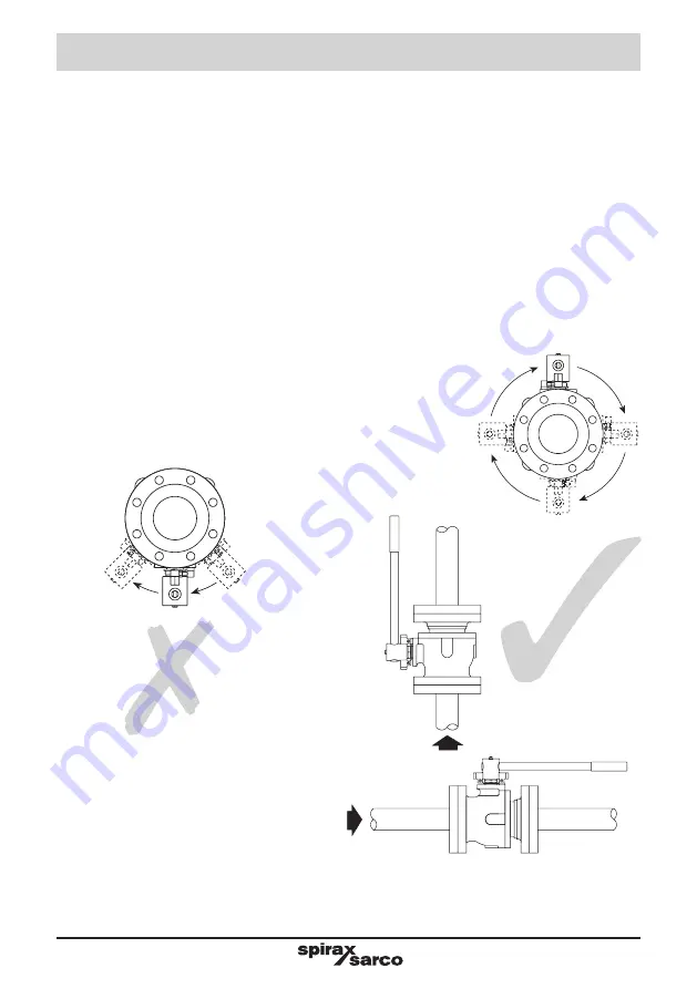
Install the valve with the handle in a suitable position. The preferred position is with the spindle vertical. The 

valve can be installed in any position for gas service (see Figure 3 below).

When used on steam services:

1. 

Fit a trapped drain pocket upstream of the valve.

2. 

Open valve slowly to prevent the risk of waterhammer damage.

Fig. 3 Correct installation for gas service

Do not mount the valve upside down 

for liquid service (Figure 2).

Fig. 2 Incorrect installation for 

liquid service

Valves should be installed into the 

pipeline in the fully closed position. 
Always open valves slowly to avoid 

system shocks.

3. Installation

Summary of Contents for M33 ISO Series

Page 1: ...2 General product information 3 Installation 4 Commissioning 5 Operation 6 Maintenance 7 Spare parts Copyright 2018 Printed in GB BAC13365 M33F ISO M33S ISO and M33V ISO Ball Valves Installation and M...

Page 2: ...other industrial fluids that are in Group 2 of the above mentioned Pressure Equipment Directive ii Check material suitability pressure and temperature and their maximum and minimum values If the maxim...

Page 3: ...o normalise after isolation to avoid danger of burns If parts made from PTFE have been subjected to a temperature approaching 260 C 500 F or higher they will give off toxic fumes which if inhaled are...

Page 4: ...e to protect products which are not self draining against frost damage in environments where they may be exposed to temperatures below freezing point 1 15 Disposal Unless otherwise stated in the Insta...

Page 5: ...When the seats have been totally destroyed the ball will come to rest firmly against the metal seat in the cap producing a metal to metal closing This secondary seat in the valve cap ensures the valve...

Page 6: ...P133 65 CMGT Issue 2 6 Fig 1 M33_ ISO 2 2 Sizes and pipe connections DN50 DN65 DN80 DN100 DN150 and DN200 Standard flange ASME B 16 5 Class 150 and 300 with face to face dimensions according to B 16...

Page 7: ...ISO 260 C 0 bar g 500 F 0 psi g Minimum allowable temperature 29 C 20 F PMO Maximum operating pressure for saturated steam service M33V ISO 10 bar g 145 psi g M33F and M33S ISO 17 5 bar g 254 psi g T...

Page 8: ...on Care must be taken to ensure that all dirt which may have accumulated in the valve during storage is removed before installation maintain cleanliness during installation since the introduction of d...

Page 9: ...ng Carry out tests on any alarms or protective devices The valve is operated manually by a handle Special care must be taken to ensure that the movement is made in the correct direction The valve can...

Page 10: ...alve from the pipeline observing the Safety information in Section 1 Warning Isolate the ball valve both upstream and downstream and wait for the unit to reach ambient temperature before handling Remo...

Page 11: ...N50 shown for the main illustration 13 Locking plate Stop plate Belville stem washers 9 Separator 1 19 4 3 5 20 2 8 7 6 4 Separator Locking plate 13 2 x Belville washers DN65 to DN200 Stop screw Screw...

Page 12: ...mended torque see Table 1 Please note If leakage is observed through the stem after 24 hours in service it may be stopped by retightening the gland nut 13 to the recommended torque see Table 1 Table 1...

Page 13: ...N50 shown for the main illustration 13 Locking plate Stop plate Belville stem washers 9 Separator 1 19 4 3 5 20 2 8 7 6 4 Separator Locking plate 13 2 x Belville washers DN65 to DN200 Stop screw Screw...

Page 14: ...tem O ring and seat O ring set 4 5 7 8 9 28 How to order spares Always order spares by using the description given in the column headed Available spares and state the size and type of ball valve Examp...

Page 15: ...IM P133 65 CMGT Issue 2 15...

Page 16: ...IM P133 65 CMGT Issue 2 16...

Reviews: