


IM-P017-03 ST Issue 5
6
Note: Before actioning any maintenance program observe
the 'Safety information' in Section 1.
6.1 General information
All work must be carried out by a suitably competent person. Before starting work ensure that
suitable tools are available. Use only Spirax Sarco replacement parts. Before attempting to
work on the air vent ensure that it is isolated from the rest of the pressurised system. Allow time
for the temperature of the air vent to normalise.
The unit has a long service life and the only maintenance that would normally be required is
the occasional cleaning of the valve and seat.
6.2 How to clean / replace the valve and seat:
-
Unscrew the cap (1) from the body.
-
The float (4) can then be detached from the lever and the mechanism removed by undoing
the screw (8) in the centre of the cap.
-
The valve cone (5) is easily changed once the float has been removed.
-
Refitting of the mechanism is straight forward, the float can then be hooked back onto the
lever and the whole assembly screwed back into the body (see Table 1 for recommended
tightening torques).
-
The set of internals are supplied with a check valve ball and circlip.
-
The check valve is only required for the AE36A.
-
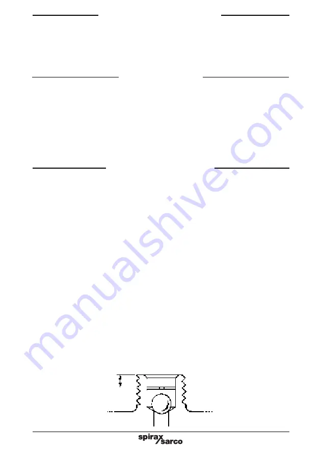
The check valve should be fitted into the outlet port and held loosely by the circlip, which
is fitted 1.6 mm below the level of the outlet as shown in Fig. 3.
After maintenance ensure that the system is fully functioning.
6. Maintenance
After installation or maintenance ensure that the system is fully functional. Carry out tests on
any alarms or protective devices.
4. Commissioning
At start-up the air eliminator / air vent is open allowing air to pass through the main valve. As
soon as water reaches the vent the float is raised and the lever mechanism closes the valve.
When more air reaches the vent it displaces water and the float falls thus opening the valve.
After the air is discharged the valve is closed, as the water level rises to replace the air.
The check valve (AE36A) is essential where there is a possibility of the system operating under
negative head conditions. It will prevent air being drawn into the system.
5. Operation
Fig. 3
1.6 mm


