6
2. Normal Operation
Once your website account is set up and you have installed your Spider you are ready to go
flying. For setting up your account, please refer to the User Guide for the Spidertracks
"
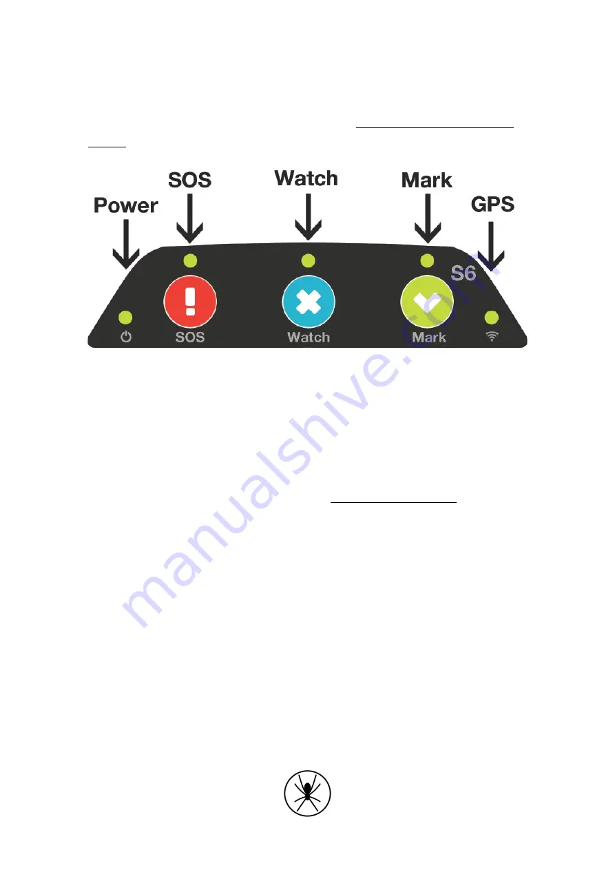
Graphic 1: Spider 6 Keypad
2.1. Initial Start Up
The Spider 6 has an LED start-up sequence to indicate the firmware. The major firmware
number is indicated by the number of flashes from left - right - left. The minor firmware
version number is indicated by number of flashes the power LED makes. The power LED will
stay on after the start-up sequence completed. To check if you have the latest firmware
version, please refer to the support article titled ‘What firmware do I have?’.
2.2. GPS Lock
The Spider 6 will automatically attempt to get a GPS fix. Once a GPS lock is attained the GPS
LED on the Spider (right LED) will turn orange.
2.3. First position point sent
When a GPS fix is attained the Spider 6 will attempt to send the first position report through
Iridium. The GPS LED will turn green afterwards.
2.4. SOS
Pressing SOS on the Spider will cause an SOS to be sent to your tier one support people setup
on the website. The only way to stop the alert is to power the Spider down and power it up
again.
Summary of Contents for Spider 6
Page 10: ...9 Appendix...
Page 22: ...21 D Wiring Diagram Power Lead...


