


8
2000 Series
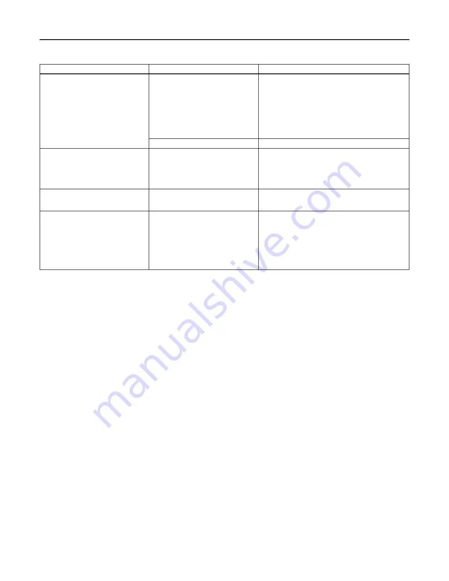
PROBLEM
VALVE TYPE
POSSIBLE CAUSES
Valve does not close
Single Seat, Direct Acting
•
Leakage through valve— note allowable leakage rate
•
Sediment trapped under seat— strainer required
•
Upstream pressure too high— check catalog for
recommended maximum pressure
•
Location of bulb in process—
1. Red dot must be in upward position
2. Change location of bulb (bulb located in “cold spot”)
poor process agitation
•
Dead system— leak in temperature system
•
Reverse acting used where direct acting is required
Double Seat, Direct Acting
See above (except c)
Valve does not open
Single Seat, Direct Acting
•
Incorrect range setting— Adjust range spring screw
•
Direct acting used where reverse acting is required
•
Location of bulb in process—
1. Red dot must be in upward position
2. Change location of bulb
•
Range °C instead of °F
Erratic Action
(Snap action or wide temperature control
band)
Single Seat
•
Valve installed with flow reversed
Poor Temperature Control
All
•
Location of bulb in process—
1. Red dot must be in upward position
2. Change location of bulb
•
Oversized valve—
1. Proper size valve will enhance temperature control
2. Oversize valve give high temperature overshoot
•
Valve installed with flow reversed (single seat only)
•
Bellows and line hotter than bulb (requires dual fill -
ranges A - D)
Table 6.
Troubleshooting
Adjustment
Unless otherwise specified, the regulator is shipped
from the factory with the adjustment nut at its lowest
position and must therefore be raised to the desired
control setting. When the temperature for which the
regulator has been set is reached, it will be maintained
automatically. After the installation is completed, preset
the regulator according to Table 3.
The operating range of the regulator is indicated
on the nameplate. The setting scale is stamped
on the side of the frame and is graduated 0 to 10
representing the limits of the operating range. This
is an arbitrary scale, since it must necessarily vary
for different temperature ranges. Table 4 gives the
approximate temperature equivalent for all scale
settings in each temperature range. The values are not
absolute and will vary from one regulator to another
because of manufacturing tolerances.
1. On initial starting, the controlled temperatures may
overshoot slightly, then drop back. Allow sufficient
time for the process to stabilize.
2.
Check the controlled temperature and make fine
adjustments. The arm extending out from the
adjusting nut indicates the temperature setting.
3. To change the temperature setting, turn the
adjusting nut up if a higher temperature is desired
and down if a lower temperature is desired. The
adjusting pin needed for this purpose is chained to
the end of the indicating arm.
On regulators equipped with a temperature indicator,
change the orientation of the indicator by loosening
the bracket retaining screws and rotate the indicator a
maximum of 180°F in either direction.
Note
All Series 2000 Regulators are provided
with a safety spring which will prevent
the bellows from expanding (even
though the valve has reached the end
of its travel) and draining the bulb
of its fill. This prevents a buildup in
vapor pressure which would damage
the bellows.
There is, however, a limiting temperature applicable
to each thermostat fill used. It is the temperature
above which the chemistry of the fill will decompose.
This limiting temperature is, therefore, the maximum
allowable temperature on 2000 Series Regulators
supplied with bulbs as indicated in Table 5.


