uX MANUAL
2
118151-001 REV A
1.2 Standard Features
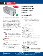
The uX series incorporates several standard features
designed to optimize user satisfaction and safety.
KV AND MA/FILAMENT CURRENT RAMP
CIRCUITS:
This feature provides for a gradual rise for
kV, mA and filament current. This feature is designed to
limit voltage shock and filament shock to the X-ray tube.
The kV ramp rate is approximately 4 seconds. The
filament current is slowly increased until the desired mA
level is achieved. This time is typically 4 seconds for full
mA output. These ramp conditions are started at the initial
INTERLOCK CLOSED control signal. Prior to closing
the Interlock the filament operates at a user determined
preheat current level. Preheat levels are selected for the
desired X-ray tube to minimize mA overshoot.
INDICATOR LEDS:
HIGH VOLTAGE ON and
POWER ON indicators.
OUTPUT CABLE:
Standard units are provided with a 1
meter shielded high voltage output cable. The cables are
designed with a plug arrangement so that they can be
easily removed from the mating receptacle located on the
front of the chassis. For non-standard units, see Spec.
Control drawing.
LOCAL AND REMOTE PROGRAMMING:
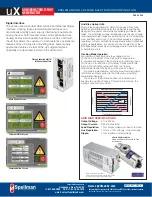
Potentiometers accessible through the top cover are
provided for controlling tube voltage, tube emission
current, tube filament limit set point and tube filament
preheat set point.
Tube voltage and tube emission current can also be
controlled remotely via the Analog Interface connector
(J4).
1.2.1 Remote Operating Features
REMOTE MONITOR:
Allows remote monitoring of
the tube voltage, tube emission current, tube filament
current, tube filament limit set point and tube filament
preheat set point via the Analog Interface connector.
EXTERNAL INTERLOCK:
Interlock connections are
provided on the Analog Interface connector on the front
of the chassis for connection to a safety switch. The unit
will not operate unless the interlock circuit is closed. The
recommended configuration is to close the interlock
circuit through a 12V lamp rated for 0.5W to 0.8W and a
safety switch. This configuration provides fail safe
interlocking. During high voltage operation, opening the
safety switch or failure of the 12V lamp will cause the
High Voltage to shut OFF. This option should be used for
safety interlock circuits.
If fail-safe interlocking of the X-ray On is not required the
lamp can be replaced with a 270 Ohm, 1 W resistor.
Provisions are provided for isolating the interlock relay
coil from the in24V, allowing the user to connect
the coil to an ex12V source. This eliminates the
need for either the lamp or the 270-Ohm resistor allowing
pin 4 to be grounded for HIGH VOLTAGE ON control.
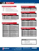
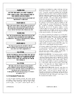
See Figure 3.4 for alternate Interlock Configurations.
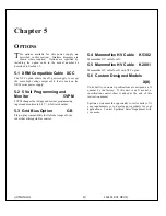
1.4 Options
CODE DISCRIPTION
•
XCC
XRM Compatible HV Cable (50kV only)
•
5VPM
0 to 5 Volt Programming and Monitor
Scaling
•
GB
Grid Bias Option.
•
K5302
Mammoflex HV cable for uX
•
K2001
Mammoflex HV cable for uX w/XCC
option
Table 1.1 uX Options
The options available are listed in Table 1.1. See Section
5 for more information on these options along with
operating and set-up instructions. With few exceptions,
these options and modifications can be retrofitted to your
power supply at the factory in a short time. For price and
retrofit arrangements, contact Spellman’s Sales
Department.
1.4 Interpreting the Model
Number:
The model number of the power supply describes its
capabilities. After the series name is:
(1) the maximum voltage (in kV)
(2) the maximum output (in watts)
(3) the option codes for all options that are included.
Custom units have an X number after the option codes.
uX 30 P 50 /XCC/ X(#)
Series
Name
Voltage
Maximum
Polarity
Option
"X" Number
Custom
Power
Maximum
Summary of Contents for uX50P50
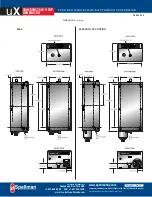
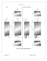
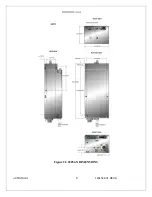
Page 16: ...uX MANUAL 4 118151 001 REV A Figure 2 1 50kV uX DIMENSIONS ...
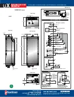
Page 17: ...uX MANUAL 5 118151 001 REV A Figure 2 2 65kVuX DIMENSIONS ...
Page 21: ...uX MANUAL 9 118151 001 REV A Table 3 2 DC Input Filament Connections ...
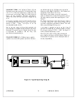
Page 22: ...uX MANUAL 10 118151 001 REV A Figure 3 3 Monitors Voltage Current Control Connections ...
Page 23: ...uX MANUAL 11 118151 001 REV A Figure 3 4 Recommended Interlock HV on Configurations ...

