background image


Spellman High Voltage Electronics Limited - Company Confidential 

This document must not be copied or distributed without express permission from Spellman High Voltage Electronics Limited


81408-4r2 MPD Series Installation and User Guide 


Page 22 of 29 


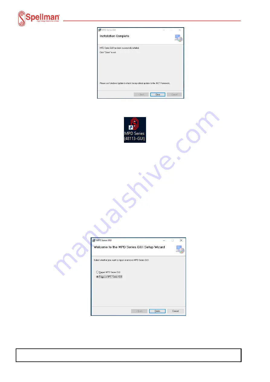
Click the ‘Close’ button. The GUI has been installed in the ‘C:\Projects\MPD_Series GUI’ 
folder on your computer and a shortcut placed on your computer’s desktop.  


Installing GUI Updates  


To install newer versions of the GUI, the old one must first be uninstalled. This can be 
done in two ways. See the following paragraphs. 
 
Note: Once the previous version of the GUI has been removed, re-install the updated one 
using the procedure in paragraph 4.2.3.1. 
 
Uninstall using the original GUI installation application. 
Execute the installation application that was used to install the application and follow the 
procedure below. 


1. Double-

click the ‘Customer 48113-GUIv

x

r

yy

.exe’ file. The GUI installer will start to 

run. 


2. 

Click the ‘Remove MPD Series GUI’ option and click the ‘Finish’ button. 

3. The application will be removed. 
4. When 

complete, a corresponding dialog will be displayed. Click the ‘Close’ button. 


Summary of Contents for MPD10N10/24

Page 1: ...ge Power Supply Modules Document number 81408 4 Issue 1 2 3 Date 19 01 2021 05 03 2021 Issuing Authority I 7632 10377P Checked Approved Tel 44 0 1798 877000 Fax 44 0 1798 872479 e mail hvsales spellmanhv co uk Broomers Park Broomers Hill Lane Pulborough W Sussex RH20 2RY ...

Page 2: ... ordering Updated approval wording 2 Contents 1 Unit Description 4 1 1 Ratings 5 2 Safety 6 2 1 Explanation of Symbols 7 2 2 Applicable standards 7 3 Installation of the Units 8 3 1 Electrical Installation 8 3 2 Mechanical Installation 8 4 Operation of the Units 10 4 1 Analogue Control 10 4 2 Digital Control 14 Appendix 1 Mechanical Outline 2 5kV to 10kV units 17 Appendix 2 Mechanical Outline 15kV...

Page 3: ... always be connected to a protective earth Do not touch connections unless equipment is turned off and the capacitance of both the load and power supply are grounded Allow adequate time for discharge of internal capacitance of the power supply Do not ground yourself or work under wet or damp conditions Servicing Safety When maintenance of equipment fitted with this power supply requires removing t...

Page 4: ...s The combination of linear and switch mode power conversion techniques provides low noise and high efficiency The unit also offers excellent ripple levels and stability The units are designed for operation from a 24V dc input and will supply up to 10W of output power The signal and power inputs and outputs are via a 15 way male D connector The HV output is via a 1m long un terminated HRG58 screen...

Page 5: ...5kV 4mA MPD2 5N10 24 2 5kV 4mA MPD5P10 24 5kV 2mA MPD5N10 24 5kV 2mA MPD10P10 24 10kV 1mA MPD10N10 24 10kV 1mA MPD15P10 24 15kV 0 67mA MPD15N10 24 15kV 0 67mA MPD20P10 24 20kV 0 50mA MPD20N10 24 20kV 0 50mA MPD30P10 24 30kV 0 33mA MPD30N10 24 30kV 0 33mA The input rating for all units is 24Vdc 2V 1A Unit masses 2 5kV to 10kV units 420g 15kV and 20kV units 650g 30kV units 950g Environmental conditi...

Page 6: ...th a UL recognised double insulated or SELV 24 V dc supply The unit shall be properly bonded to the main protective earthing termination in the end product The unit has been evaluated for use in a Pollution Degree 2 Installation Category II environment Consideration should be given to conducting the following tests with the unit installed in the end product a Permissible Limits Tests with the unit...

Page 7: ...d User Guide Page 7 of 29 2 1 Explanation of Symbols This symbol means Caution consult the manual This symbol indicates the Protective Earth PE terminal This symbol means Caution hot surface 2 2 Applicable standards The unit is designed to meet the requirements of EN 61010 1 UL 61010 1 and CAN CSA 22 2 No 61010 1 Please consult the factory for further approval information This symbol means Caution...

Page 8: ...main protective earthing termination in the end product The input and output connectors are not intended for field connections and should only be connected to internal wiring in the end product All external circuits connected to High Voltage outputs shall be Double Reinforced insulated from any accessible parts The connector details on the standard unit are shown in table 1 overleaf 3 2 Mechanical...

Page 9: ...o 10 Vdc equals 0 to 100 of rated output Zout 10kΩ 7 Voltage Program Differential Amplifier Input Positive 0 to 10 Vdc differential between pin 7 and pin 9 equals 0 to 100 of rated output diode clamped to ground Zin 38kΩ 8 Current Monitor Output 0 to 10 Vdc equals 0 to 100 of rated output Zout 10kΩ 9 Voltage Program Differential Amplifier Input Negative 0 to 10 Vdc differential between pin 7 and p...

Page 10: ...trol and Monitoring Signals The units are controlled and monitored using the following analogue signals PARAMETER MIN VALUE MAX UNITS Voltage control 0 to 10V 0 to Full scale output V i 1 1 Voltage reference output wrt signal ground 10 V Enable Active low enable input impedance Designed to be operated by TTL or CMOS logic or open collector transistor 10 kΩ Voltage monitor 0 10V for 0 to full scale...

Page 11: ...It prevents voltage drops in the ground connection from affecting the programming signal However if there are voltage drops in the ground connection the DAC should be provided with its own reference 24V Power input on Pin 2 Power Common on Pin 1 0 to 10V voltage control signal to Pin 7 Signal ground reference for 0 to 10V control signal Connected to signal ground for 0 to 10V voltage control also ...

Page 12: ...rential input when the voltage control circuit is close to the power supply however it is important to connect all grounds at Pin 1 of the PSU to prevent voltage drops in the ground circuit from affecting the programming signal Take care to avoid ground loops 24V Power input on Pin 2 Power Common on Pin 1 DAC output to Pin 5 DAC ground to Pin 11 Connect Pin 4 to the DAC reference input Connect Ena...

Page 13: ...nce on Pin 4 and ground with the wiper connected to Pin 5 this will allow the potentiometer to be used to control the unit The user should note the use of a potentiometer may affect the performance of the MPD unit The unit may be controlled by an external potentiometer as follows 24V Power input on Pin 2 Power Comon on Pin 1 Connect Pin 4 to external pot CW Connect Pin 11 to external pot CCW Conne...

Page 14: ...e slaves The following parameters apply PARAMETER MIN VALUE MAX UNITS Digital Mode RS232 or RS485 Low RS485 Open circuit RS232 Enable Active low enable input impedance Designed to be operated by TTL CMOS logic or open collector transistor or software command 10 kΩ Voltage control resolution 16 Bit Monitor resolution 16 Bit The following sections describe the circuits used for RS232 and RS485 to ma...

Page 15: ...y D connector For the protocol used refer to protocol document 48113 21 which can be provided on request The unit may be controlled digitally as follows 24V Power input on Pin 2 Power Common on Pin 1 Select Mode RS232 on Pin 13 by leaving open circuit RS232 signal ground on pin 11 RS232 transmit on Pin 14 connect to Rx pin on PC RS232 receive on Pin 15 connect to Tx pin on PC Connect Enable Pin 12...

Page 16: ...be provided on request The unit may be controlled digitally as follows 24V Power input on Pin 2 Ground on Pin 1 Select Mode RS485 connected Power common to Pin 1 RS485 signal ground on Pin 11 RS485 Z inverting on Pin 14 connect to RS485 inverting pin Z or B on PC RS485 Y non inverting on Pin 15 connect to RS485 non inverting pin Y or A on PC A 120R termination resistor should be fitted to the last...

Page 17: ...cs Limited 81408 4r2 MPD Series Installation and User Guide Page 17 of 29 Appendix 1 Mechanical Outline 2 5kV to 10kV units 130 0 70 0 Fixing face 15w D plug Customer Adjust Point 70383 46 0 14 0 49 0 28 0 MOUNTING HOLE TEMPLATE NOTE Max thread depth into unit is 5mm TOP OF UNIT 7 0 Unit Footprint 30 0 SIDE OF UNIT CALIBRATION VOID IF SEAL BROKEN HOLE Ø3 5mm IN 3 POSITIONS ...

Page 18: ...nics Limited 81408 4r2 MPD Series Installation and User Guide Page 18 of 29 Appendix 2 Mechanical Outline 15kV 20kV units 165 0 70 0 Fixing face 15w D plug Customer Adjust Point 70927 46 0 14 0 49 0 28 0 MOUNTING HOLE TEMPLATE NOTE Max thread depth into unit is 5mm TOP OF UNIT 7 0 Unit Footprint 30 0 SIDE OF UNIT CALIBRATION VOID IF SEAL BROKEN HOLE Ø3 5mm IN 3 POSITIONS ...

Page 19: ...ompany Confidential This document must not be copied or distributed without express permission from Spellman High Voltage Electronics Limited 81408 4r2 MPD Series Installation and User Guide Page 19 of 29 Appendix 3 Mechanical Outline 30kV units ...

Page 20: ...e communications protocol for the MPD unit is specified in the Spellman document 48113 21 Serial Communications Protocol GUI Requirements The GUI is written to run on Microsoft Windows 10 and uses Microsoft Net Framework Version 4 The GUI makes use of the Windows Registry to hold application configuration information Your IT team MUST ensure the GUI has permission to access to the following area o...

Page 21: ...procedure below 1 Copy the files above to a convenient location on your computer 2 Double click the Customer 48113 GUIvxryy exe file The GUI installer will start to run 3 Click the Next button The End User License Agreement EULA will be displayed Read the EULA through and if you agree to the terms click the I Agree button and then click the Next button The installer is now ready to install the GUI...

Page 22: ...UI the old one must first be uninstalled This can be done in two ways See the following paragraphs Note Once the previous version of the GUI has been removed re install the updated one using the procedure in paragraph 4 2 3 1 Uninstall using the original GUI installation application Execute the installation application that was used to install the application and follow the procedure below 1 Doubl...

Page 23: ...s Features tool To uninstall the application using the Apps Features tool follow the procedure below Click the Windows 10 task bar search icon The Search text box will be displayed 1 Start to enter the text apps The search results will display the item below Click this item The Settings GUI will be displayed showing the Apps Features page 2 Scroll down the list and find the MPD Series GUI 3 Click ...

Page 24: ... a shortcut to the GUI will have been placed on the Windows 10 Desktop Double click the shortcut icon to launch the GUI GUI Configuration Before attempting to communicate with the MPD the GUI must first be told which serial comms port to use To do this follow the procedure below 1 Click the Setup menu option on the GUI menu bar The dialog box shown below will be displayed 2 Select the serial port ...

Page 25: ...n be seen the GUI contains many controls that are grouped into areas The following paragraphs briefly discuss each of these groups of controls Monitoring the MPD Unit Various groups of controls are provided to monitor the MPD outputs and status Output Monitors The controls shown below display the current operating status of the HV output voltage and current monitors along with the 24V rail and tem...

Page 26: ...bled when both the SW Enabled and HW Enabled flags are green as shown in the Status field The HW enabled requires a signal as defined in the table 1 in Section 3 2 To SW enable the output check tick the check box a short time afterwards the indicator to the right of the check box will change colour See below Enabled Disabled Programming Output Demand Programming the MPD output is achieved using th...

Page 27: ...ogramming GUI as below i Select the Serial Com Port to be used ii Set the Baud Rate to 19200 Baud iii Check the RS485 Enable checkbox iv Select the Slave Address of the unit to be programmed Note Select the slave address the module has been programmed with Click the Connect button Click the Load Hex File button browse to and select the MPD firmware 48113 14 The inactive buttons are now active Clic...

Page 28: ...lication code is running Prerequisites i Connect serial comms to and power up the unit Run the MPD GUI 48113 GUI Click the Set up menu option The Set up dialog box will be displayed Click RS232 and select the serial Comms port to use Click OK when finished Click the Diagnostics tab Set the Slave Address to the address the unit is programmed with Click the Upload New Firmware button A command will ...

Page 29: ...the unit Run the MPD GUI 48113 GUI Click the Single Unit tab The GUI will look similar to the image below Click the Get Address button The GUI data fields will start to be populated Press the CTRL A keyboard buttons together Answer Yes to the prompt Some additional controls will be displayed Enter the address the unit is to be set to and click the Set Address button When prompted click the Yes but...

Reviews: