background image

Message Area  ................................................................................13
Top Speed  ......................................................................................14
Current Speed  ................................................................................14
Current Lean Angle  ........................................................................14

System Menu   ........................................................................................14

Timer Mode  ....................................................................................................16

Introduction  ............................................................................................16
Auto Features  .........................................................................................16
Knowing the Buttons  ..............................................................................17
GPS Positioning and Auto Search  .........................................................17
If No Track Is Found  ...............................................................................17
If There Are Tracks Found ......................................................................18
Selecting A Track To Use Manually  ........................................................19
Activatng Auto Set Track 15 Manually  ....................................................19
Starting Timer and Data Logging  ...........................................................19
Stopping Timer and Data Logging  ........................................................ 20
Viewing Your Lap Time Report  ............................................................. 20
Advanced: Setting a Better Finish Line with Auto Set  ........................... 21

How A Finish Line Is Set with Auto Set  ......................................... 21
How to Control Your Finish Line Location  ..................................... 21
Stay Close to the Center Line  ....................................................... 22
Adjust Line Width Beforehand If Necessary  .................................. 22

Linear Track  .......................................................................................... 22

Configuring the Timer 

 ........................................................................... 23

Connecting GMOS to a Computer  ................................................................ 26

TROUBLE SHOOTING  ...............................................................................28

WARRANTY  ............................................................................................... 31

SPECIFICATION  .........................................................................................32

Summary of Contents for GMOS JI100S

Page 1: ...JI100 SERIES USER MANUAL Version 0320 2015 for Firmware 59 and above SpeedAngle Inc www SpeedAngle com ...

Page 2: ...one of normal bike movement or the long axis of the motorcycle body does not point to the traveling direc tion ahead due to twist The GMOS Core is constantly examining if such interaction exists every time a turn is completed If the answer is yes it will compensate the interac tion and re produce measurement results after the calibration As the records of the Angle History and Max Angle fields are...

Page 3: ...MPS pattern Mount 5 With a Hand made Mount 6 Installing Sensor 7 Location 7 Installation Orientation 8 Signs That the Installation Is Not Correct 8 Installation Checklist 9 Connecting Sensor to Dashboard 9 USING GMOS 10 Charging GMOS 10 Getting Started 10 Drive Mode 11 Icons and Their Functions 11 GPS Antenna Icon 11 REC Icon 11 Temperature Alert 12 Battery Icon 12 Current Time 12 G force Bar 12 L...

Page 4: ...tivatng Auto Set Track 15 Manually 19 Starting Timer and Data Logging 19 Stopping Timer and Data Logging 20 Viewing Your Lap Time Report 20 Advanced Setting a Better Finish Line with Auto Set 21 How A Finish Line Is Set with Auto Set 21 How to Control Your Finish Line Location 21 Stay Close to the Center Line 22 Adjust Line Width Beforehand If Necessary 22 Linear Track 22 Configuring the Timer 23 ...

Page 5: ...ber The registration number can be found at the back of your GMOS dashboard unit or on the Welcome Screen Introduction and Functions GMOS JI100S is a state of the art data logger developed for motorcycle enthusi asts It is capable of recording not only your track performance but also the motion and trace of your ride Equipped with cutting edge 10Hz GPS module and aero 1 1 Dashboard unit and Bracke...

Page 6: ...y Up to 7 Sector Lines in one Track uploaded via software SpeedAngle R4 Up to 15 Tracks Track editable via software Lap time record report with motion data Google 3D replay with SAtoKML converter All the data can be recorded in the built in memory for up to 7 hours or 254 logs whichever is reached first After your ride connect the GMOS dashboard unit to your PC to have the logged data downloaded O...

Page 7: ...d Menu Button press to enter menu or in a menu to go to the next item LED blinks on when battery is charging Select Button press to start stop recording or in a menu to execute the function or adjust the value Sensor Connection Cable USB Port Power Switch Backlight Switch Bracket The holes marked at the ends of the red lines conform to AMPS hole pattern a pat tern adopted by many mount manufacture...

Page 8: ...ARD AND OR SENSOR WITH ANY DEVICE OTHER THAN COMPUTERS OTHERWISE THEY MIGHT BE HARMED Sensor The sensor must be installed parallel to the bike body vertical to the ground with UP pointing upward and FRONT toward the front of the bike Sensor Connection Cable ...

Page 9: ...n either use the supplied 3M Dual Lock tape and adhere the bracket to a place you like or buy an AMPS hole pattern mount from the market and bolt the bracket to the mount With 3M Dual Lock Tape To use clean the mounting surface and the back of the brack et with alcohol and wipe dry Keep the SA logo rightside up Apply the joined pieces to the back of the bracket and press the bracket to the mountin...

Page 10: ... mount plate no problem The hole pattern on the bracket is designed to form as many equilateral triangles and squares as possible to allow you the maximum freedom when adjusting fitting orientations Below are two examples After the bracket is installed insert the left end of the device into the bracket then click the right end into place 1 2 ...

Page 11: ... and vertical to the ground on the main frame near the footpeg Top View Rear View Parallel to the bike body center line Vertical to the ground If you would like to install it elsewhere follow the principles above and avoid places that may move swing wag turn or vibrate such as handle bar bike tail and fairing etc Wheel Exhaust Pipe Suspension Handle Bar Fairing Tail ...

Page 12: ... installation location if you see the lean angle meter needle moving erratically during a turn in Drive Mode or you see such lean angle graph pattern as the figure to the right in the analysis software SpeedAngle R4 If your angle shows a similar graph pattern in R4 as below the sensor is installed in a wrong direction Make sure the FRONT on the sensor case is pointed to the front of the bike The b...

Page 13: ... make sure the arrows on the cable heads align with each other Insert the plug into the receptacle until you hear a click Connect the sensor before you turn the device power on NOTE If the sensor is connected AFTER the power is on it will not be recognized by the device You can choose not to connect the sensor and use the dash board alone as a simple lap timer In this case no lean angle data will ...

Page 14: ...an empty battery Keep it in an environment near 20 C 68 F Otherwise the battery life might be reduced severely Getting Started When GMOS is powered on you will see the Welcome Screen appear displaying your User ID can be edited via SpeedAngle R3 GMOS model and its registration number for 5 seconds You can press any key to skip the wait Then GMOS will display the Liability Screen Please read it car...

Page 15: ...nctions 1 GPS Antenna Icon indicates the quality of GPS signal reception The more vertical lines the icon displays the better the reception and thus the higher the positioning accuracy If there are less than 4 satellites locked the GPS Antenna Icon will not be displayed This will not interrupt ongoing log recording However if this hap pens when you are pressing SELECT to start a new log the system...

Page 16: ...he operating temperature range of the sensor 36 F 140 F or 2 C 60 C flashes when the temperature is below 36 F 2 C while flashes when the tempera ture is above 140 F 60 C Environmental temperature below or above the sensor s operating tempera ture range might affect measurement accuracy 4 Battery Icon indicates the charge of the battery When the battery is almost empty a LOW BATTERY message will b...

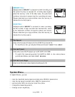
Page 17: ... right 69 degrees 10 Message Area displays messages about log recording The message will be displayed for about 2 seconds There are five messages that may appear in the Message Area START LOGGING END LOGGING displayed when GMOS starts ends data recording This is an additional reminder besides the REC icon POSITIONING displayed when SELECT is pressed to start recording but there are not enough sate...

Page 18: ...to release the memory space 11 Top Speed shows the top speed measured since GMOS is powered on To clear the record go to System Menu and select RESET TOP SPEED 12 Current Speed shows the current GPS speed up to 255 MPH 410 KMH To switch the measuring system from MPH to KMH or vice versa please go to System Menu and select UNIT MPH KMH 13 Current Lean Angle shows real time lean angle degree reading...

Page 19: ...s SELECT to clear the memory A SURE mes sage will be prompted Press SELECT again to con firm or press MENU to cancel Once the memory is cleared the number of logs dis played at the top of the menu will be down to 0 and the memory left be back to 100 Press SELECT to change the LCD brightness Press SELECT to enter Lap Timer Mode A SURE message will be prompted Press SELECT again to confirm or press ...

Page 20: ...dinal G Angles are not displayed The lower half consists of three compo nents Main Display Sub Display and Lap number Auto Features Youe SpeedAngle lap timer is basically hands free The best way to use it is turn on the power and then DO NOTHING unless you have multiple settings available for the track and need to choose one Focus on your ride It will take care of itself With convenience in mind t...

Page 21: ...h for available tracks settings either by Auto Set or by preloading whose reference point is within 3 KM 1 8 mile of your location During this process you can press MENU to enter Laptimer Menu and edit set tings but this is not recommended until you are familiar with the Menu Auto Search will be executed only once To run Auto Search again please reboot GMOS and enter Timer Mode again If No Track I...

Page 22: ...are more than one Track found GMOS will list them and wait 90 seconds so that you have time to select one Press MENU to go to the Track you want and then press SELECT to confirm Then GMOS will enter Standby Mode MENU MENU SELECT SELECT 12 30 TOP 0KMH SACUIT WEST TIMER STARTS AT 90KMH PLEASE SELECT ONE SACUIT EAST SACUIT WEST 08_25_12 14 38 SET A NEW TRACK 12 30 PLEASE SELECT ONE SACUIT EAST SACUIT...

Page 23: ... TRK 01 SACUIT WEST START TIMER 90KMH STOP TIMER 20s IDLE LINE WIDTH 100M 12 30 Activatng Auto Set Track 15 Manually If you regret your choice and would like GMOS to set a new Track press MENU in Standby Screen to enter Laptimer Then follow the steps below Press MENU to go to SET FL AT TRACK15 Press SELECT to switch it on Exit the Menu GMOS will prepare to set a new Track at or overwrite Track15 E...

Page 24: ...d period of time You can control when the data logging is to end by setting a proper idle time Here are a few suggestions Timer stop condition Suggested Idle Time Shortly after you stop riding 10 sec Stay running even during your wait on the grid 180 or 240 sec Please note that if your idle time is set at above 30 when you have been idle for more than 30 seconds after start riding such as when you...

Page 25: ... draws a line extending 50M from the reference point to both sides perpendicular to your trace This is your Finish Line Then GMOS also marks your riding direction as the valid crossing direc tion of this Line This is to prevent unwanted Lap times when the Line is crossed from a wrong direction Then GMOS will go on to start the Timer How to Control Your Finish Line Location As the location where th...

Page 26: ... to make sure the Line does not extend to the next neighboring lane and cause unwanted crossings set the reference point outside the track so that the line does not extend to the next neighboring lane wrong crossing Line Width 60M This can done with SpeedAngle R4 Track Manager For more information please see the tutorial video on www speedangle com download SpeedAngle R4 sec tion Linear Track The ...

Page 27: ...mer Menu you can view the Lap Time Report of up to 14 latest logs activate Auto Set to set a new Track at Track 15 later designate a Track to use later designate the Timer starting speed designate at what idle time the Timer is to stop designate the length of the Finish Line designate what is to be displayed as Main Display or Sub Display and designate how long the Main Display and Sub Display are...

Page 28: ...racks avail able and designate one to use later Press SELECT to choose a speed at which GMOS is to set a Finish Line start the Timer and start log recording You can choose a value between 10 and 240 by an increment of 30 For how to choose a proper starting speed please refer to Advanced Setting a Better Finish Line with Auto Set P 21 12 30 LAPTIMER 12L 75 LEFT VIEW LATEST RECORD SET FL AT TRACK15 ...

Page 29: ...Finish Line at 60M or 100M long Press SELECT to designate what is to be used as Main Display between Lap Time and Session Time Press SELECT to designate what is to be used as Sub Display among Best Lap with time gap time gap displayed after a lap is complete Last Lap and Sec tor Time if there are Sector Lines available Press SELECT to choose a time length the Main Dis play and Sub Display are to b...

Page 30: ... R4 Double click on the USB driver to start installation 2 Connect the dashboard unit and your computer with the sup plied USB cable Power on your GMOS dashboard unit GMOS will enter USB mode automatically and display USB CON NECTED on the device screen 3 If this is your first time connecting to this computer your Windows will search for the driver and install it automatically Wait till it shows Y...

Page 31: ...h as preloading track settings or modifying Finish Line location after a log has been recorded please watch the tutorial videos on www SpeedAngle com Download SpeedAngle R4 section GMOS utilizes high speed download to save download time If you are download ing with a laptop and are encountering download errors please set the battery management plan to HIGH PERFORMANCE If you are using communicatio...

Page 32: ...bove Make sure the installation location does not move turn swing wag or vibrate too much For more information please see the Installing Sensor section Make sure you are using the red sponge tape included in the box to install the sensor Do not use the Dual Lock tape It will create extra vibration Please also make sure that the environmental temperature is within 36 F 140 F 2 C 60 C Using GMOS out...

Page 33: ...ero when I was riding at a constant speed Please check to see if the sensor is installed vertical to the ground securely A tilted sensor might affect G force and lean angle measurement If it stayed maxed out the indicator inside the G sensor was stuck Please give the sensor a few light taps and it will be back to zero Q Why was there no lap time produced when I passed through a Finish Line This mi...

Page 34: ... you did not cross the Finish Line in the new session there was no new lap and thus no new record Q Why was the USB CONNECTED message not prompted when my GMOS was connected to my PC Please make sure you use the supplied USB cable 5 pin male mini USB and that the USB cable is connected to the USB ports of the computer and the dash board unit securely Also make sure the power is on Q I cleared the ...

Page 35: ...pping label are valid for 30 days from their issue date To ship the GMOS device back for warranty service please follow the instructions below Please ship the GMOS device in its original or equally protective package with a copy of the original packing slip or the PayPal invoice Please print and cut out the issued shipping label and adhere it to the top of the package A package without the issued ...

Page 36: ...me 14 hrs with backlit off Logs 254 logs max Max Log Time about 7 hrs Log Resolution 20 pps for lean angle and G 10 pps for GPS and speed Lap Timer Resolution 1 1000 second GPS Antenna built in GPS Update Rate 10 Hz GPS Sensitivity 167 dBm tracking GPS Channels 72 all in view GPS Cold Start Time 26 sec average GPS Speed 255 MPH 410 KMH max Longitudinal G Range 1 5 G Lean Angle Range R L 69 Feature...

Page 37: ...t backlit and external GPS Antenna Logs 254 logs max Max Log Time about 7 hrs Log Resolution 20 pps for lean angle and G 10 pps for GPS and speed Lap Timer Resolution 1 1000 second GPS Antenna built in and external GPS Update Rate 10 Hz GPS Sensitivity 159 dBm tracking GPS Channels 32 all in view GPS Start Time 36 sec average GPS Speed 255 MPH 410 KMH max Longitudinal G Range 1 5 G Lean Angle Rang...

Reviews: