


16
Measurement
Procedure
Recording the best quality data requires some practice.
Your objective is to uniformly push the probe into the
ground using an even motion. The programmed
rate,specified in the ASAE standards, is approximately
2 seconds per 2 inches. If this rate is exceeded, the
meter will show an Error display (see Warning Mes-
sages pg. 18).
To take a profile measurement:
1. Push and release Start button.
2. Wait for LCD to display the profile information
screen. The top line shows the current cone index
and the depth. At the surface the depth will be
zero. The second line indicates how many profiles
have been taken. This resets to 1 every time the
meter is turned on.
3. Stand with your feet at least 4 to 6 inches from the
probe tip. This ensures the sonic depth sensor will
measure accurately. Tall, nearby objects or walls
will also inhibit the ability of the depth sensor to
“see” the ground surface. If you are working in turf
or an especially uneven soil surface, you may need
to use a target to ensure reliable performance (see
Depth Sensor p. 5). It is advisable to smooth the
soil surface as much as possible before inserting the
probe. As the probe is inserted into the soil, the
0010 PSI 00 IN
N=1
Profile Information Screen
13
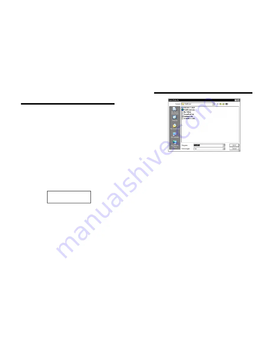
Download
To download data from the internal data logger, turn
the meter off and connect the gray serial cable to the
RS-232 port on the underside of the meter. Click the
Download button on the main software screen. In the
Save Data As screen, give the file a descriptive name
and select the location where it will be saved.
When the file has been saved, the software will give
you the option of immediately viewing the file. The
data file is stored as a comma-delimited text file and
may be viewed in text editor or spreadsheet software.
Clear Memory
Data is not automatically removed from the logger
memory after a download. The Clear Memory button
clears all data from the logger memory.
Meter Settings
Click this button to configure the meter and data log-
ger. Refer to Meter Settings (p. 14) for more details.
Main Toolbar (Cont.)
Main Toolbar (Cont.)
Main Toolbar (Cont.)
Main Toolbar (Cont.)