Speco HFB4M Instruction Manual Download Page 21

- 21 -

3. BACKLIGHT

On this menu, backlight image can be compensated by users selecting one of modes. (HLC, BLC, WDR) 

1. Move the triangular indicator to BACKLIGHT on the SETUP menu screen using the Up and Down button.

2. Select the desired mode by using the left or Right button.

◆ 

Off : Deactivated status

.

◆ 

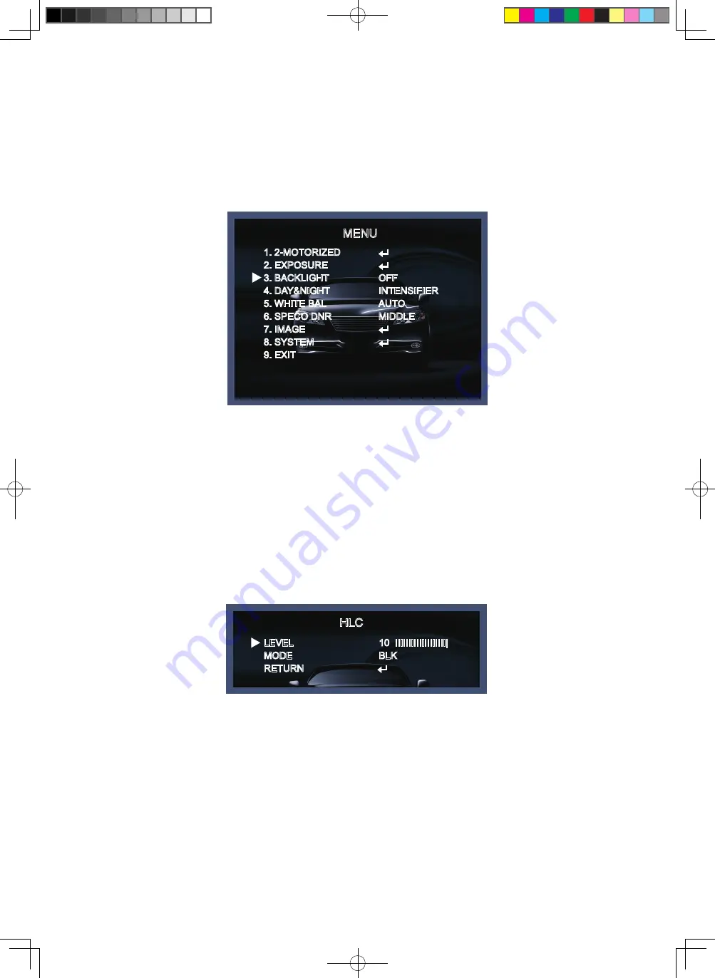
HLC : This function is used to surpress or strong light source (for example, headlights of cars during

      nighttime) so that other subjects can be seen in more detail. If you select HLC, a submenu appears

      where you can make finer adjustments.   

   - LEVEL : Adjust the brightness level from which on the light source is to be masked out.
     0~20 level adjustable.
   - MODE : Select the color of HLC range.

HLC

LEVEL
MODE
RETURN

10  IIIIIIIIIIIIIIIIIII| 
BLK

◆ 

BLC : This function is used to counterbalance the screen image by increasing the brightness so that a 

      subject which appears dark due to a strong backlight can be displayed in more detail. If you select BLC, 

      a submenu appears where you can make finer adjustments.

   - H-POS/V-POS/H-SIZE/V-SIZE : Define the position and size of the area of interest by changing the position
     & size.

MENU

1. 2-MOTORIZED
2. EXPOSURE
3. BACKLIGHT
4. DAY&NIGHT
5. WHITE BAL
6. SPECO DNR
7. IMAGE
8. SYSTEM
9. EXIT

OFF
INTENSIFIER
AUTO
MIDDLE

Speco(Fit).indd   21

2020-05-21   오전 9:52:24

Summary of Contents for HFB4M

Page 1: ...s Camera Speco Technologies is constantly developing product improvements We reserve the right to modify product design and specifications without notice and without incurring any obligation Rev 01 01...

Page 2: ...s 2 Precautions 3 4 Safety Instructions 5 Package Contents 6 Camera Installation 7 10 Specifications 11 12 Camera Dimension 13 Features 14 OSD Menu Details 15 28 Trouble Shooting 29 Speco Fit indd 2 2...

Page 3: ...ally careful to provide ventilation when operating under high temperatures This is one of the most important parts of the camera Be careful not to leave fingerprints on the lens cover It can cause mal...

Page 4: ...ion against harmful interference when the equipment is operated in a commercial environment This equipment generates uses and can radiate radio frequency energy and if not installed and used in accord...

Page 5: ...a other than to make initial adjustments Use a UL approved regulated 24 volt AC or 12 volt DC power supply Use appropriate low voltage power cable to prevent fire or electrical shock Please insure tha...

Page 6: ...1 Power Jack 1 Mount Base Sticker 1 Wrench Set Screw 3 Tapping Screws 4x25 4 Hexagon Socket Screws M4x14 3 Plastic Anchor 2 HFD4M Included Junction Box 1 Power Jack 1 Chameleon Cover 1 Junction Box Sp...

Page 7: ...USING 12 VOLTS DC constant voltage 500mA 2 WHEN USING 24 VOLTS AC 40 Volt Amps 3 CONNECT VIDEO CABLE CONNECT BLACK COLOR BNC CABLE TO THE BNC JACK D C 12V P ower S upply P ower Input R E D C enter L...

Page 8: ...8 Camera Installation Compatibility 1 HFB4M 2 HFD4M INTCM INTCM INTWM Speco Fit indd 8 2020 05 21 9 52 14...

Page 9: ...era Installation 9 1 HFB4M WALL ANCHOR WHT 6X30 PLASTIC 4EA JUNCTION BOX SCREW TAP SLV SUS BH_4X25 TP1 3EA SCREW MS WHT SUS PH_M4X10 3EA SCREW MS WHT SUS PH_M4X14 4EA Speco Fit indd 9 2020 05 21 9 52...

Page 10: ...Camera Installation 10 2 HFD4M Speco Fit indd 10 2020 05 21 9 52 15...

Page 11: ...nsor 2616 H X 1964 V 5 14M Pixels 2704 H X 2104 V 5 69M Pixels 720P 1080P 1440P 1944P NTSC 30P PAL 25P 20P 12 5P Progressive Scan 0 01 Lux F1 2 TVI CVBS More than 50dB 2 8 12mm Motorized Lens with Aut...

Page 12: ...nsor 2616 H X 1964 V 5 14M Pixels 2704 H X 2104 V 5 69M Pixels 720P 1080P 1440P 1944P NTSC 30P PAL 25P 20P 12 5P Progressive Scan 0 01 Lux F1 2 TVI CVBS More than 50dB 2 8 12mm Motorized Lens with Aut...

Page 13: ...13 Camera Dimension 1 HFB4M 2 HFD4M 3 14 4 76 3 74 9 4 76 3 85 3 4 3 14 4 76 3 74 9 4 76 3 85 3 4 Speco Fit indd 13 2020 05 21 9 52 21...

Page 14: ...ras you can enjoy vivid image in any dark condition Sens Up Despite a limited low light condition Sens Up Max x32 helps the viewer to get visible and clear images Defog Defog function improves the cla...

Page 15: ...0P 0 20 default 10 BLK WHT YEL CYN GRN MAG RED BLU 0 20 default 11 0 19 default 10 0 20 default 3 0 12 default 3 LINE FRAME OFF BOX POLYGON LOW MIDDLE HIGH WINDOW ZONE WINDOW USE H POS V POS H SIZE V...

Page 16: ...0 20 default 13 0 20 default 3 LOW MIDDLE HIGH 0 20 default 2 ON OFF 0 10 default 10 0 20 default 13 0 20 default 7 LOW MIDDLE HIGH 3000K 5000K 8000K 0 20 default 10 0 20 default 10 MODE LEVEL RETURN...

Page 17: ...AME RATE FREQ CONFIRM RETURN SAVE CANCEL FULL COMP USER ENG CHN CHN S JPN KOR OFF RIGHT UP LEFT DOWN ON PUSHING OFF TVI 720 30P 1080 30P 1440 30P 1944 20P 1944 12 5P 50HZ 60HZ YES PUSH OFFSET RETURN P...

Page 18: ...lation environment The Advaned Set Up menu will be displayed on the monitor SPECO TECH 1 PRESET 2 MAIN SETUP 3 EXIT INDOOR MENU 1 2 MOTORIZED 2 EXPOSURE 3 BACKLIGHT 4 DAY NIGHT 5 WHITE BAL 6 SPECO DNR...

Page 19: ...t button 1 2 MOTORIZED 1 2 MOTORIZED AF MODE D N FILTER INITIALIZE RETURN ONESHOT SYNC OFF ON AF MODE ONESHOT Adjust zoom and focus automatically MANUAL Adjust zoom and focus manually D N FILTER ON OF...

Page 20: ...shutter speed can be adjusted from 1 30 to 1 50 000 FLK Select FLK mode if flickering occurs caused by the unmatched frequency of electric light SENS UP The bright screen can be displayed by sensing t...

Page 21: ...EVEL Adjust the brightness level from which on the light source is to be masked out 0 20 level adjustable MODE Select the color of HLC range HLC LEVEL MODE RETURN 10 IIIIIIIIIIIIIIIIIII BLK BLC This f...

Page 22: ...1 1080 You can select the vertical size of the monitoring area POLYGON WINDOW ZONE 0 3 WINDOW USE ON OFF POS0 X You can select the horizontal Diagonal starting position of the monitoring area POS0 Y...

Page 23: ...ss automatically under the circumstance of low light condition or at night SMART IR 0 20 smart IR level adjustable GHOST_CAT ON OFF Get rid of Ghost phenomenon image dragging when set up the SENS UP L...

Page 24: ...he manual compensation mode and then press Set button While looking at the color change of the subject seen on the screen after setting up the proper color temperature increase the each value of the b...

Page 25: ...the left or Right button and OFF LOW MIDDLE HIGH level selectable 7 IMAGE When selecting the following submenu will appear Here you can optimise the image quality by adjusting different options MENU...

Page 26: ...ting level control to over come even strong backlight conditions DEFOG ON OFF This function helps to recognize the object in a dusty weather condition ON a submenu appears where you can make finer adj...

Page 27: ...arting position of the monitoring area POS0 Y You can select the vertical Diagonal starting position of the monitoring area POS1 X You can select the horizontal Diagonal starting position of the monit...

Page 28: ...hanged IMAGE RANGE Adjust the rate of YC signal to 100 FULL 75 COMP or 100 75 USER LANGUAGE ENG CHN CHN S JPN KOR CAM TITLE It can be adjusted when you get into the Cam Title menu This function is to...

Page 29: ...mptom then please manually move the control board once to the left and once to the right Then the focusing will be corrected and working properly as it should 2 Recommendation ONE PUSH Feature In case...

Page 30: ...30 Speco Fit indd 30 2020 05 21 9 52 27...

Page 31: ...Speco Fit indd 31 2020 05 21 9 52 28...

Page 32: ...200 New Highway Amityville NY 11701 631 957 8700 1 800 645 5516 www specotech com Speco Fit indd 32 2020 05 21 9 52 28...

Reviews: