


Operating Instructions
16
1096.0799 | VU / VH Series
10/2010
5.6.3
Specifying pipe lengths
1.
Dimension the suction, pressure and operating liquid pipes
as short as possible.
2.
Increase the pipe cross-sections when using long suction,
pressure and operating liquid pipes.
The pressure pipe must not rise more than 1 m vertically or
diagonally upwards.
5.6.4
Changes in cross-section and direction
1.
Avoid radii of curvature of less than 1.5 times the nominal
pipe diameter.
2.
Avoid sudden changes of cross-section and direction along
the piping.
5.6.5
Safety and control devices
5.6.5.1 Avoiding
contamination
1.
Integrate low-resistance filters in the suction pipe.
2.
Install a differential pressure gauge with contact manome-
ter to monitor the contamination process.
5.6.5.2 Avoiding
backflow
►
Install a ball check valve between the suction pipe and the
suction connection of the aggregate to prevent operating
liquid from flowing back into the suction pipe after aggre-
gate shut-down.
5.6.5.3
Provisions for isolating and shutting off pipes
For maintenance and repair works
►
Provide for shut-off devices in the suction, pressure and
process water pipes.
5.6.5.4
Provisions for measuring operating conditions
1.
For pressure measuring: provide for manometers in the
suction and pressure pipe.
2.
Provide for a power sensor at the motor side.
5.7 Connecting
pipes
5.7.1
Providing for clean piping
CAUTION
Risk of material damage caused by pump/aggregate con-
tamination!
►
Make sure contamination does not enter the
pump/aggregate.
1.
Clean all piping parts and fittings prior to assembly
2.
Make sure no flange seals project inwards.
3.
Make sure no sealing material (sealing tape, adhesive)
projects inwards.
4.
Remove any blank flanges, plugs, protective foils and/or
protective paint from the flanges.
5.7.2
Installing suction pipe
1.
Remove the transport and sealing covers from the
pump/aggregate.
2.
Avoid air pockets: lay out the pipes with a continuous slope
down to the aggregate.
3.
Make sure no seals project inwards.
4.
Make sure no sealing material (sealing tape, adhesive)
projects inwards.
5.
Install a ball check valve in the suction pipe to prevent
operating liquid from flowing into the suction pipe at stand-
still.
5.7.3
Installing pressure pipe
1.
Remove the transport and sealing covers from the
pump/aggregate.
2.
Install the pressure pipe.
3.
The pressure pipe must not rise more than 1 m vertically or
diagonally upwards.
4.
Avoid air pockets: lay out the pipes with a continuous slope
from the aggregate.
5.
Make sure no seals project inwards.
6.
Make sure no sealing material (sealing tape, adhesive)
projects inwards.
5.7.4
Stress-free pipe connection
For the layout of piping, observe VDMA standard sheet
24277 on stress-free pipe connections.
5.8 Fine adjustment of coupling
CAUTION
Risk of material damage caused by improper coupling ad-
justment!
►
Accurately adjust the motor to the pump in case of height,
lateral or angular offset.
►
For detailed information and special couplings:
(
Manufacturer's specifications).
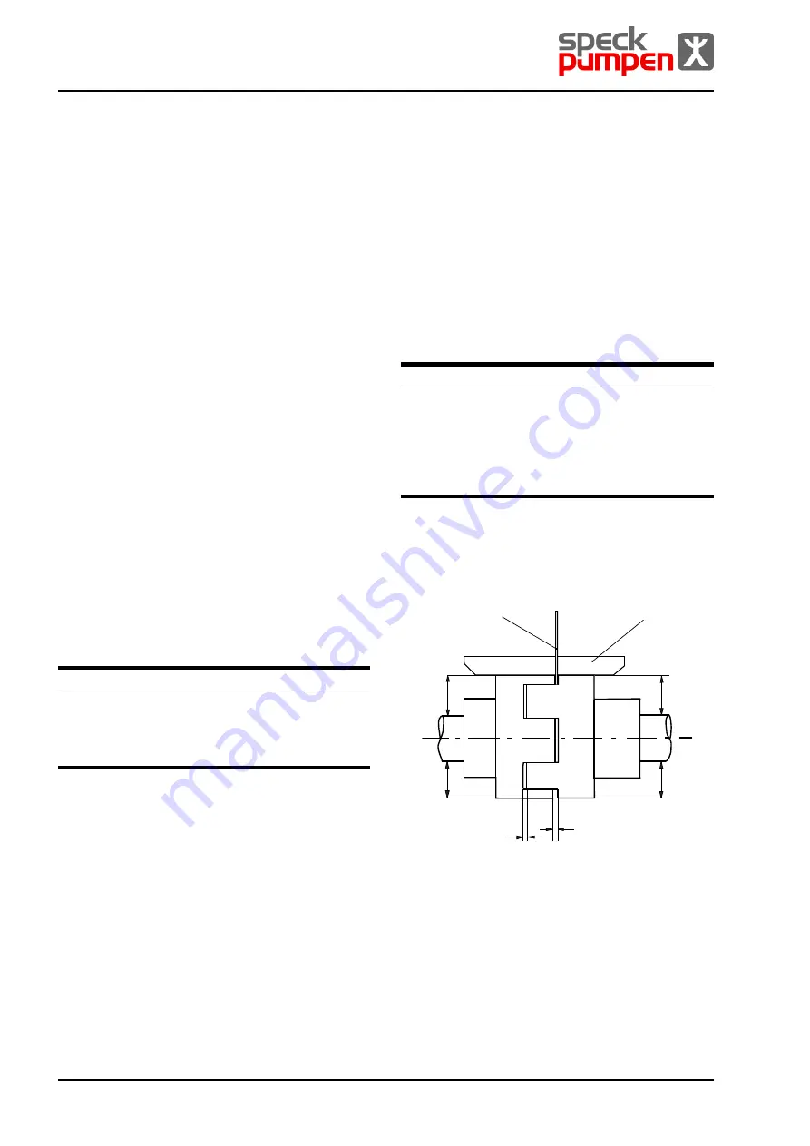
5.8.1
Checking coupling adjustment
Auxiliary means, tools, material:
feeler
gauge
straightedge
dial gauge (possible with couplings with spacer)
other suitable tools, e.g. laser adjustment tool
2
B
B
A
A
S
S
1
1 Gauge
2 Straightedge
Fig. 12 Checking coupling adjustment


