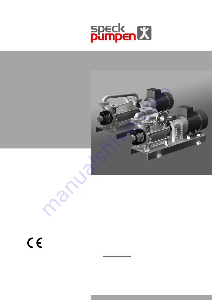
Speck pumpen VH 110 Operating Instructions Manual Download Page 1


Operating Instructions 

VU / VH Series 

VU 20 - 1600 
VH 20 - 1600 
Liquid Ring Vacuum Pumps 


English translation of the original operating 
instructions 


Documentation 

It is imperative to read the operating instruc-
tions prior to commissioning!  
This document as well as all documents in-
cluded in the appendix is not subject to any  
update service! 
Subject to technical changes. 

Speck Pumpen Vakuumtechnik GmbH

Regensburger Ring 6 – 8, 91154 Roth / Germany 
PO Box 1453, 91142 Roth / Germany 
Phone:  +49 (0) 9171 809 0 
Fax: 

+49 (0) 9171 809 10 

E-mail: 

[email protected]


Internet: 

www.speck-pumps.de


Issue: 
10/2010 

Supersedes issue: 
06/2010 

Doc./ Item no.: 
1096.0799 


Summary of Contents for VH 110

Page 1: ...r to commissioning This document as well as all documents in cluded in the appendix is not subject to any update service Subject to technical changes Speck Pumpen Vakuumtechnik GmbH Regensburger Ring...

Page 2: ...6 5 6 4 Changes in cross section and direction 16 5 6 5 Safety and control devices 16 5 7 Connecting pipes 16 5 7 1 Providing for clean piping 16 5 7 2 Installing suction pipe 16 5 7 3 Installing pres...

Page 3: ...mes 45 9 7 Test pressure for pressure test 45 9 8 Accessories 45 10 Appendix 46 10 1 Dimension drawing VU 20 40 46 10 2 Dimension drawing VU 80 140 220 47 10 3 Dimension drawing VU 300 450 48 10 4 Dim...

Page 4: ...tructions to third parties requires written approval of the manufacturer This also applies to the duplication or transfer of excerpts of these operat ing instructions and to the transfer of these oper...

Page 5: ...additional provisions and regulations related to the system Qualified staff assembler Read observe and adhere to these operating instructions and all applicable documents particularly the safety preca...

Page 6: ...easures marked with the safety sign to avoid personal injuries or death by electric shock Instruction for action 1 2 Multi step instruction for action Pre requisite Cross reference Information note Ta...

Page 7: ...gregates have been expressly intended for such purpose Unauthorized opening of the pump aggregate results in the forfeiture of any and all claims for defects 2 3 General safety instructions The follow...

Page 8: ...ed out at standstill Prior to carrying out any assembly or maintenance works de energize the motor and protect it against restart Having completed all works on the pump aggregate duly re assemble the...

Page 9: ...escription The pumps of the VU series are horizontal liquid ring vacuum pumps with a single stage and radial suction pressure connec tion The internal control of the media to be pumped is realized by...

Page 10: ...e lower density in the hub area As the impeller is positioned off centre to the casing the available space for the gas between the surface of the liquid and the hub becomes crescent shaped This way th...

Page 11: ...30 25 20 25 20 Lifting Women 16 17 19 20 45 45 13 13 15 13 9 9 10 9 8 9 8 Carrying Men 16 17 19 20 45 45 20 30 50 40 13 20 30 25 15 20 15 Carrying Women 16 17 19 20 45 45 13 13 15 13 9 9 10 9 8 9 8 L...

Page 12: ...ug all drainage bores with screw plugs Remove the pipes from the suction pressure and process water connections Plug the outlet nozzle and the process water connection by means of blank flanges screw...

Page 13: ...ing agent according to local regulations 4 For storage periods exceeding 6 months Replace elastomer components made of EP rubber EPDM Check all elastomer components O rings shaft seal ings for proper...

Page 14: ...g agent If the pump aggregate is commissioned directly after set up and connection remove preserving agent prior to set up Removing preserving agent page 13 5 2 Set up with foundation Only possible wi...

Page 15: ...cks and bumps Do not tilt the coupling halves when slipping them on Do not knock on or hit any pump components 1 Apply a razor thin layer of molybdenum disulfide e g Molykote on the pump and motor sha...

Page 16: ...l piping parts and fittings prior to assembly 2 Make sure no flange seals project inwards 3 Make sure no sealing material sealing tape adhesive projects inwards 4 Remove any blank flanges plugs protec...

Page 17: ...0 and for potentially explosive areas the IEC 60079 DIN VDE 0165 standard DANGER Risk of death from rotating parts Make sure to only operate the aggregate with all covers fan hood installed 5 10 1 Mot...

Page 18: ...aggregate Do not touch the running aggregate Do not carry out any works on the running aggregate RISK OF ELECTRIC SHOCK Risk of death from electric shock Any electrical works must be carried out by q...

Page 19: ...nder vacuum If the aggregate is not aerated the mechanical seals will be subject to damage 6 3 Setting the operating liquid flow rate 6 3 1 Continuous flow cooling Switch on the aggregate Set the pres...

Page 20: ...tes the aggregate at intervals of at least one month but not exceeding three months Commissioning page 18 shut down for a longer period of time Implement measures in accordance with the condition of t...

Page 21: ...sible leaks at the shaft sealing proper functioning of the auxiliary operating systems if available 3 Check shaft sealing Mechanical seals are maintenance free sealing systems In case of leaks Have th...

Page 22: ...n carrying out any works on the pump aggregate Make sure the pump aggregate is depressurized Drain the pump Reliably collect operating liquid and media to be pumped and dispose of in an environmentall...

Page 23: ...1 and 137 2 Remove the ring 500 and the packing gland 461 from the inter casings 137 1 137 2 7 5 5 Disassembly of VU 80 140 220 VH 110 140 180 Cross sectional drawing VU 80 220 Cross sectional drawin...

Page 24: ...047 1 off the pump shaft 211 Pull off the spacer sleeve 525 6 Disassembly of suction casing Rotate the pump 90 drive side pointing up Loosen the nuts 920 920 1 remove the nuts and the casing bolts 563...

Page 25: ...de Remove the fitting key 940 from the pump shaft 211 Loosen the hexagon head screws 901 2 901 4 pull the bearing housing 330 with the rolling bearing 320 off the pump shaft VU VH 500 600 Pull off the...

Page 26: ...total air gap must also be ensured when replacing parts Inter casings and impellers must be adjusted to each other if required Please verify that the spring of mechanical seal 047 is always right han...

Page 27: ...sing bolts 563 and slightly fasten them with hexagon nuts 920 Press fit the rolling bearing 320 into the bearing housing 330 Force the bearing cover 360 into the bearing housing 330 and adjust fasten...

Page 28: ...th lu bricant alcohol water Manually push the stationary unit 047 1 into the shaft sealing casing 411 Adjust the shaft sealing casing 441 observe the flushing channel force it into the discharge casin...

Page 29: ...PTFE Push the rotating unit 047 onto the pump shaft 211 by a screwing movement in the sense of winding of the spring Moisten the auxiliary seal of the stationary unit with lu bricant alcohol water Ma...

Page 30: ...onto the pump shaft Set the impeller in accordance with adjustment dimen sion L by turning the impeller nuts Following the setting process check adjustment di mension tighten the impeller nuts and sec...

Page 31: ...force it into the suction casing 106 Adjust the inter casing 137 3 marks and force it into the discharge casing 107 Screw hexagon socket head screws 914 through the suction discharge casing into the...

Page 32: ...tationary unit 047 1 into the shaft sealing casing 411 Adjust the shaft sealing casing observe the flushing channel force it into the discharge casing 107 and fasten it with hexagon head screws 901 1...

Page 33: ...maintenance staff is not able to rectify the defect the manufacturer has to be informed accordingly The manufacturer will provide troubleshooting support if he gets a detailed description of the defec...

Page 34: ...the suction pipe and connections Wrong direction of rotation of the motor Check direction of rotation swap the 2 phases if need be Insufficient vacuum Leaking system Check the system seal leaking spot...

Page 35: ...h Excessive operating liquid flow rate Reduce operating liquid flow rate Overload in the pipe system Check the pipe connections pump fixa tion bearing clearance of the pipe clamps Air pocket in the pi...

Page 36: ...perating limit values VU 20 40 VU 80 140 220 Pressure mbar Operating liquid Min inlet pressure 150 Temperature C Perm compression pressure 1200 Max 100 Perm pressure difference Min 10 Max 1500 Density...

Page 37: ...id Min inlet pressure 120 Temperature C Perm compression pressure 1500 Max 80 Perm pressure difference Min 10 Max 1600 Density kg m 3 Min 200 Max 1200 Medium to be pumped Viscosity mm 2 s Temperature...

Page 38: ...uid Min inlet pressure 33 Temperature C Perm compression pressure 1500 Max 80 Perm pressure difference Min 10 Max 1500 Density kg m 3 Min 200 Max 1200 Medium to be pumped Viscosity mm 2 s Temperature...

Page 39: ...0 570 VU 1600 520 VH 1600 640 Tab 20 Weight 9 2 2 Sound level Type 1m measured surface sound pressure level L dB A 50 Hz 60 Hz VU 20 40 66 67 VU 80 140 220 65 66 VU 300 450 351 451 66 68 VU 500 600 76...

Page 40: ...e delivery of water via the inlet nozzle 9 2 4 3 Filling volume Type Flow rate l min 80 mbar 15 C Max liquid delivery m 3 h Filling vol ume up to middle of the shaft l VU 20 4 8 0 29 0 9 VU 40 5 6 0 3...

Page 41: ...00 Flange DN 100 Flange Tab 24 Operating connections 9 2 7 Mechanical seal All pumps offer mechanical seals with integrated flush Typical features are single seal unbalanced conical spring dependent o...

Page 42: ...s Tightening torque Nm M 5 A2 A4 4 2 M6 A2 A4 7 3 M 8 A2 A4 17 5 M 10 A2 A4 35 M 12 A2 A4 60 M 16 A2 A4 144 M 20 A2 A4 281 Tab 29 Tightening torques for stainless steel screws in stainless steel casin...

Page 43: ...0 M 16 90 M 20 120 M 24 140 Tab 35 Tightening torques for casing bolts 9 3 Conical pipe fittings The above specified tightening torques do not apply to conical screw in threads Here tightness is not a...

Page 44: ...ance free and need not be adjusted Pump types VU 300 1600 and VH 500 1600 are equipped with spherical roller bearings Versions with cylindrical bores need not be adjusted Spherical roller bearings are...

Page 45: ...ox 15 VU 450 11 7 approx 25 VU 451 10 0 approx 24 5 VU 500 11 7 approx 25 VU 600 13 5 approx 29 VU 800 31 0 approx 65 VU 1200 34 0 approx 72 VU 1600 36 5 approx 78 Tab 42 Preservation filling volumes...

Page 46: ...s Spare parts designation and position cross sectional drawings Certificate of conformity EC declaration of conformity 10 1 Dimension drawing VU 20 40 Fig 22 Dimension drawing VU 20 Fig 23 Dimension d...

Page 47: ...imension drawing VU 80 Fig 25 Dimension drawing VU 140 Fig 26 Dimension drawing VU 220 Designation Explanation UB Operating liquid connection Ue Ue1 Drainage screw plug UL Ventilation valve connection...

Page 48: ...450 Fig 27 Dimension drawing VU 300 Fig 28 Dimension drawing VU 450 Designation Explanation UB Operating liquid connection Ue Ue1 Drainage screw plug UL Ventilation valve connection Um Manometer conn...

Page 49: ...Dimension drawing VU 351 Fig 30 Dimension drawing VU 451 Designation Explanation UB Operating liquid connection UC Connection for cavitation protection Ue1 Ue2 Drainage screw plug UiF Adjusting screw...

Page 50: ...600 Fig 31 Dimension drawing VU 500 Fig 32 Dimension drawing VU 600 Designation Explanation UB Operating liquid connection Ue Ue1 Drainage screw plug UL Ventilation valve connection Um Manometer conn...

Page 51: ...sion drawing VU 800 Fig 34 Dimension drawing VU 1200 Fig 35 Dimension drawing VU 1600 Designation Explanation UB Operating liquid connection Ue Ue1 Drainage screw plug UL Ventilation valve connection...

Page 52: ...ension drawing VH 20 Fig 37 Dimension drawing VH 40 Fig 38 Dimension drawing VH 60 Designation Explanation UB Operating liquid connection Ue Ue1 Drainage screw plug UL Ventilation valve connection Um...

Page 53: ...nsion drawing VH 110 Fig 40 Dimension drawing VH 140 Fig 41 Dimension drawing VH 180 Designation Explanation UB Operating liquid connection Ue Ue1 Drainage screw plug UL Ventilation valve connection U...

Page 54: ...nsion drawing VH 300 Fig 43 Dimension drawing VH 350 Fig 44 Dimension drawing VH 400 Designation Explanation UB Operating liquid connection Ue Ue1 Drainage screw plug UL Ventilation valve connection U...

Page 55: ...600 Fig 45 Dimension drawing VH 500 Fig 46 Dimension drawing VH 600 Designation Explanation UB Operating liquid connection Ue Ue1 Drainage screw plug UL Ventilation valve connection Um Manometer conn...

Page 56: ...mension drawing VH 800 Fig 48 Dimension drawing VH 1200 Fig 49 Dimension drawing VH 1600 Designation Explanation UB Operating liquid connection Ue Ue1 Drainage screw plug UL Ventilation valve connecti...

Page 57: ...peller 320 Rolling bearing 330 Bearing housing 360 2 Bearing cover 400 1 Sealing 411 1 2 Sealing ring 441 Shaft sealing casing 500 1 Ring 507 Splash ring 525 Spacer sleeve No Designation 550 1 Washer...

Page 58: ...mpeller 320 Rolling bearing 330 Bearing housing 360 2 Bearing cover 400 Sealing 411 2 Sealing ring 441 Shaft sealing casing 500 Ring 507 Splash ring 550 1 Washer No Designation 562 Cylindrical pin 563...

Page 59: ...sing 360 2 Bearing cover 400 1 Sealing 411 3 Sealing ring 412 O ring 441 Shaft sealing casing 500 1 Ring 507 Splash ring 524 Shaft protection sleeve 525 Spacer sleeve No Designation 531 Withdrawal sle...

Page 60: ...320 Rolling bearing 330 Bearing housing 360 2 Bearing cover 400 1 Sealing 411 1 2 Sealing ring 441 Shaft sealing casing 500 1 Ring 507 Splash ring 523 Spacer sleeve 525 Spacer sleeve No Designation 55...

Page 61: ...0 2 Bearing cover 400 1 Sealing 411 3 Sealing ring 412 O ring 441 Shaft sealing casing 461 Packing gland 500 1 Ring 507 Splash ring 524 1 Shaft protection sleeve 525 Spacer sleeve No Designation 531 W...

Page 62: ...ned both inside and outside in accordance with the operating instructions Further handling of the pump aggregate does not require special safety precautions The following safety precautions must be ob...

Page 63: ...Operating Instructions 10 2010 1096 0799 VU VH Series 63 10 18 EC declaration of conformity...

Reviews: