Slip Joint
Wrench
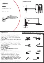
INSTRUCTIONS FOR MODELS
92-SB-2531-33-02
For additional assistance or service please contact:
SPEAKMAN
®
800-537-2107
www.speakman.com
SB-2531
SB-2533
HELPFUL TOOLS & SUPPLIES:
TOOLS AND SUPPLIES
Drill
Hole Saw
2.5mm Hex
Key Wrench
(Included)
Level
Adjustable
Wrench
Flat Tip
Screwdriver
Thread Seal
Tape
Measuring
Tape
Safety
Glasses
Supply
Hoses
Slip Joint
Wrench
Warranty information can be found at:
www.speakman.com
WARRANTY
MAINTENANCE
SAFETY TIPS
IMPORTANT
• Be sure to read instructions thoroughly before
beginning installation.
• Cover the installation area(s) as deemed
necessary to prevent any loss of parts.
Your new Speakman Product is designed for years of
trouble-free performance. Keep it looking new by
cleaning it periodically with a soft cloth. The use of harsh
chemicals and abrasives on any of the Speakman custom
finish products may damage the finish and void the
product warranty. Please be sure to only use approved
cleaners. Please contact Speakman for any clarification
of acceptable cleaners.
IMPORTANT
• Do not over-tighten any connections or damage
may occur.
• Shut off the water supply before beginning
installation.
• This installation manual covers several models.
While your models may look different, it will install
in the same manner.
• This Faucet has an operating range of 20-80 psi.
•
CAUTION:
Risk of personal injury. Do not use
the bath filler as a grab bar or support bar when
entering or exiting the bath. The bath filler is not
designed to support weight.
• Observe all local plumbing and building codes.
• Use appropriate drill bits for wood and/or other
materials.
1
1
2
3
4
5
8”-12”
[203mm-305mm]
-1"
[22mm-25mm]
5”-6”
[127mm-152mm]
5”-6”
[127mm-152mm]
CAUTION:
Always turn off the water supply before removing an existing faucet or replacing any part of a faucet.
Open the faucet handle to relieve water pressure and ensure that the water is completely shut off.
• Shut-off the Water supply.
• Drill Holes in the finished Deck as shown in the diagram below.
NOTE:
This kit allows up to 1-3/4
”
Deck thickness.
SITE PREPARATION
2
NOTE:
HOT Endbody is clearly marked to identify for future steps.
Loosen, but do not remove, the Set Screws using the included Hex Key Wrench. Remove Handle and Flange
assemblies and put aside for later use.
2.5mm
REMOVE HANDLE AND FLANGE ASSEMBLIES
3
❶
Unthread and remove the Mounting
Collars from the HOT and COLD Endbodies,
as well as the Diverter Valve Body.
❷
Ensure that the Mounting Nuts, Metal
Washers, and Rubber Washers are threaded
down to the base of the HOT and COLD
Endbodies, as well as the Diverter Valve Body.
❸
Remove the Sleeve, Mounting Nut, Metal
Washer, and Rubber Washer from the Hand
Shower Support.
REMOVE MOUNTING COLLARS
4
• From below, insert the HOT Endbody through
Hole 1
.
❶
Reinstall the Mounting Collar and secure into
position using a Slip Joint Wrench on the flats of the
Mounting Collar.
❷
Hand tighten the Mounting Nut, Metal Washer, and
Rubber Washer into position. Do not wrench tighten at
this time.
• Repeat process for the COLD Endbody into
Hole 3
.
• Align Endbodies as shown below.
HOLE
1
HOLE
3
HOT
ENDBODY
COLD
ENDBODY
TUB
HOT/COLD VALVE BODY INSTALLATION
5
❶
From below, insert the Diverter Valve Body through
Hole 4
. Reinstall Mounting Collar and secure into
position using a Slip Joint Wrench.
• Align Diverter Valve Body so that the
“H”
and
“C”
markings are facing towards the Tub.
❷
Hand tighten the Mounting Nut, Metal Washer, and Rubber Washer into position.
Do not wrench tighten at this time.
TUB
HOLE
4
DIVERTER VALVE BODY INSTALLATION