- 35 -
2.8. Overheat discharge valve
Since the heating for the H
2
O fireplace insert is not automatic and cannot
be quickly switched off, the hot water attachment must be equipped with
an overheat discharge valve in accordance with DIN 4751 – Part 2 or DIN
EN 12828 to prevent hazardous situations in the event of a fault, e.g., a
power failure. A safety device is installed for this purpose in the H
2
O
fireplace insert (safety heat exchanger) to protect against overheating.
This safety device must not be used as a water heater.
The overheat discharge valve supplied (e.g., SYR, type 3065) is tested
and approved for a minimum water flow rate of 900 kg/h. The sensor on
the capillary tubing must be inserted and permanently fixed in the
connection opening of the H
2
O fireplace insert (in the sealed-in immersion
sleeve) that is marked accordingly.
The following points must always be observed during installation to
ensure the safety device can work properly:
During installation the enclosed installation and operating manual
supplied by the overheat discharge valve manufacturer must be fol-
lowed!
The fittings of the overheat discharge valve may only be installed in
the feed pipe. This is to ensure that there is no standing water in the
safety heat exchanger when used as intended.
The fittings of the overheat discharge valve must
not
be sited in the
hot area of the heat chamber (convection chamber) of the fireplace
system (max. ambient temperature 80°C). Select the position on the
basis of the length of the capillary tubing.
A minimum flow pressure of 2.0 bar must be available at the cold
water intake. This pressure must be maintained at all times. Fluctua-
tions in water system pressure must not occur. This means, for ex-
ample, that supply from a domestic water system that is itself de-
pendent on the mains supply is
not
permitted.
A minimum water flow rate of approx. 900 kg/h must be ensured. It
must not be possible to shut off this supply pipe.
The heating insert must be aligned so that the front bleed valve is at
the highest point.
All safety-relevant components must be integrated in the system in such a
manner that checks may be carried out on their operation and for possible
leaks at any time. The discharge of the overheat discharge valve must be
executed in such a manner that a test may be carried out at any time (e.g.
via an outlet with siphon).
- 36 -
2.9. Thermal pump control system
The fireplace insert must always be used with a load unit. A JUMO or
Afriso thermostat switch is also supplied with the cell. This must be
electrically integrated into the power supply of the load unit (circulating
pump).
The appropriate rolled-up capillary tube should be unrolled and inserted
into the marked immersion sleeve at the top front right/left and secured
with the clip supplied.
Ensure there are no kinks in the capillary tube!
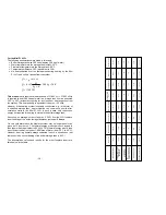
This switch ensures that the circulating pump only cuts in if the water
temperature is adequate and is switched off again if the temperature
drops below the specified level. The connection is made as shown in
Fig.
4a-b
. Control of the circulating pump by means of a boiler control system
or similar device is not recommended. During installation the enclosed
installation and operating manual for the thermostat must be followed. The
thermostat sensor must be inserted and permanently fixed in the
connection opening of the H
2
O fireplace insert (sealed immersion sleeve)
that is marked accordingly.
The maximum loading capacity of the thermal pump control system is
approx.
500 W
at 230 V AC.
The factory setting of the minimum thermostat can be adjusted by means
of the control dial and has been preset to a range of approx. 62°C to
approx. 72°C. The start-up temperature of the pump is set on this
thermostat. Optionally, if conditions so warrant, the setting range can be
adjusted by the company performing installation. If the control dial is
removed, the setting range can be varied by moving the locking disc,
which can be reseated in a different position by removing the screws. In
the minimum setting (the locking disc is fastened through the holes
marked “min”), the setting range can be adjusted from approx. 57°C to
approx. 67°C.
Please note
: The minimum setting of approx. 57°C may result in values
below the dew point. The maximum setting (locking disc fastened through
the holes marked “max.”) ranges from 67°C to 77°C.
The JUMO heatTHERM fittings must
not
be sited in the hot area of the
heat chamber (convection chamber) of the fireplace (max. ambient
temperature 80°C). Select the position in the cold area on the basis of the
capillary tubing length!
Summary of Contents for Mini Z1 H2O
Page 5: ...9 Mini Z1 H2O Fig 1a 10 Mini Z1 H2O XL Fig 1b...
Page 6: ...11 Mini Z1h H2O XL Fig 1c 12 Varia 1V H2O Fig 1d...
Page 7: ...13 Varia 1Vh H2O Fig 1e 14 Varia 1V H2O XL Fig 1f...
Page 8: ...15 Varia 1Vh H2O XL Fig 1g 16 Varia 1V H2O XXL Fig 1h...
Page 9: ...17 Varia 1Vh H2O XXL Fig 1i 18 Varia 2Lh 2Rh H2O Fig 1j...


